
Arduino CAN Bus Interface
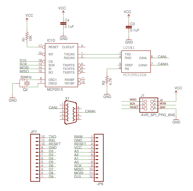
The circuit design is straightforward, employing an SPI interface to connect to the MCP2515 CAN Controller IC, which manages the low-level operations of the CAN protocol, including timing, arbitration, and error detection. The design closely mirrors Sparkfun's CAN Shield, maintaining pin compatibility but opting for a 20MHz ceramic resonator instead of the 16MHz oscillator utilized in the original design. This choice was made based on available components and may potentially enhance performance at higher bit rates, although this has not been empirically tested.
The shield's design allows for compatibility with various CAN Shields, as they share a similar interface with Arduino, facilitating the use of common software across different implementations. Notably, the MISO, MOSI, and SCK lines were connected to the six-pin ISP programming header due to the unique configuration of the Arduino Leonardo, which does not expose these signals to the standard headers. This approach is intended to ensure functionality across different Arduino models, although testing has not been conducted on other types.
The schematic includes an MCP2515 positioned to the right and an MCP2551 at the top center. A DB-9 connector, repurposed from a serial cable, connects to pins 2 and 7. The design also incorporates a small pushbutton switch on the proto board, with two holes connected to ground used to secure the serial cable. Additionally, an LM34 temperature sensor is included to provide an analog input for testing the CAN-FIX software. The assembly features two rows of female headers for the ISP interface, constructed from modified single-row headers due to the unavailability of dual-row components. Overall, the circuit is designed to be simple yet effective for testing and development purposes.Implementation of CAN for use in aircraft. The protocol is called CAN-FIX and is a part of the MakerPlane Open Source Airplane project. You can get more information on CAN-FIX here. The idea for this project is to build an Arduino shield that will let it communicate over the CAN bus. I had some Microchip MCP2515 and MCP2551 (CAN Controller and CANTransceiver, respectively) laying around so I decided to make my own little Arduino shield so that I could quickly try out some ideas. I started with the little ProtoShield that Sparkfun sells. I also had some header material laying around so just getting the PCB without the rest of the kit worked for me.
An easier answer may be to get the full ProtoShield Kit. This will give you some buttons and LED`s to play with too. My intention for this particular device is to use it as a generic USB<->CAN converter. Once I have that working, I`ll have a CAN interface for a computer and could use the same code with an Arduino Mini, or something similar, to interface to a Beagleboard, Rasberry Pi or other SBC. The circuit is pretty simple. It`s just an SPI interface to the MCP2515 CAN Controller IC. This IC handles all of the low level details of the CAN protocol. Things like timing, arbitration, error detection etc are all offloaded to this IC. I purposely made mine similar to the CAN Shield that Sparkfun sells. The pins are the same but I choose to use a 20MHz ceramic resonator instead of the 16MHz oscillator that`s on the CAN Shield.
The only reason I did that was because I had some. It might make it work better at higher bit rates too but I haven`t tested any of that to know. There are a couple of CAN Shields out there and they all have basically the same interface to the Arduino so this means that we should all be able to use the same software with all of them. After all an SPI interface to the MCP2515 seems to be the most popular way to do CAN communication anyway.
One thing about my shield that is a bit odd is how I actually tied in the MISO, MOSI and SCK lines. Since I decided to try this with a new Arduino Leonardo which has some differences in where these signals are located. They don`t bring them out to the headers any more, so I connected them to the six pin ISP programming header.
This should work regardless of which type of Arduino used but I haven`t tried it on another type. In this shot you can see the MCP2515 to the right and the MCP2551 in the top center. The DB-9 connector is just one end of a serial cable that I had lying around (You can`t see it in this picture, but it`s on the other end of that thick black cable). I just cut one end off of it and found pin 2 and 7 for use here. There is a pad on the proto board for a small pushbutton switch. I used two of those holes (the ones tied to GND) as place to solder some wire and hold the serial cable.
There are probably better ways. The transistor looking thing to the left is an LM34 temperature sensor. I threw it on there so that I`d have something analog on the board to use when I`m playing around with the CAN-FIX software. In the above image you can see the two rows of female headers that I used for the ISP interface. I didn`t have any two row female headers so I just cut a couple of single row headers and jammed em together.
As you can see there really isn`t much to it. 🔗 External reference
Related Circuits

RS-232 Serial Interface Status Indicator Circuit. This circuit utilizes a single logic integrated circuit (IC) to indicate the transmission (TXD) and reception (RXD) statuses of a serial interface. The RS-232 Serial Interface Status Indicator Circuit is designed to provide visual...
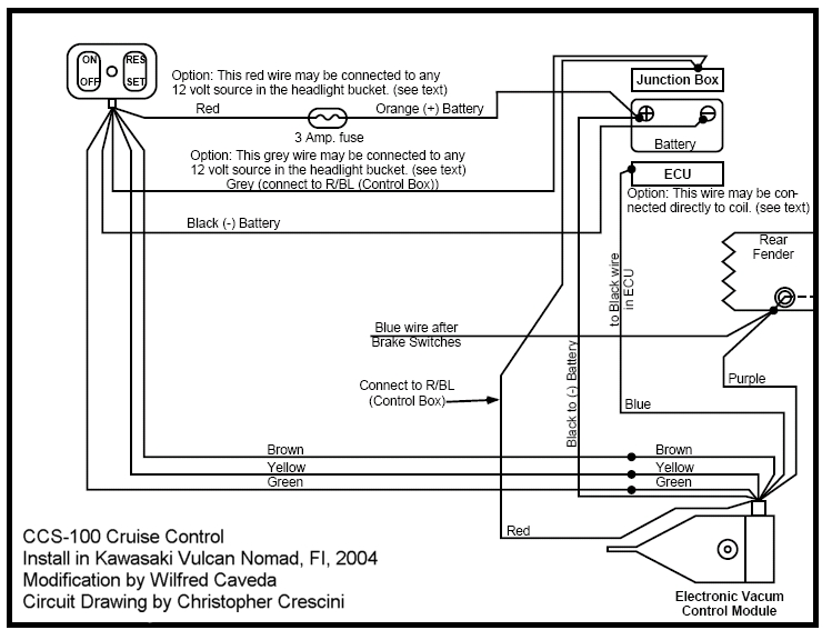
This project involves significant electrical wiring and requires modifications to the left side cover box, including drilling holes and making a slot. The gas tank must be removed, and careful reading of the instructions is essential. The Audiovox instruction...
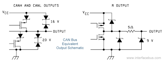
The Controller Area Network (CAN) Interface is a balanced (differential) two-wire interface that operates over Shielded Twisted Pair (STP), Unshielded Twisted Pair (UTP), or ribbon cable. Each node in the network utilizes a male 9-pin D connector. The bit...
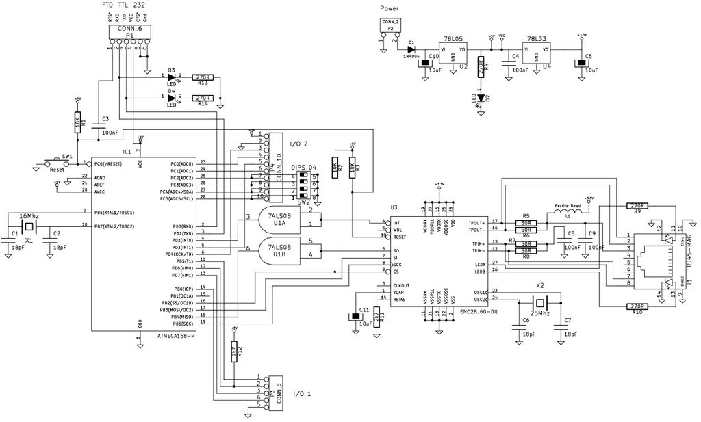
The Arduino is a simple and accessible controller platform suitable for various projects. A few months ago, an Ethernet shield was purchased for it. The Arduino platform is widely recognized for its user-friendly interface and versatility, making it a popular...
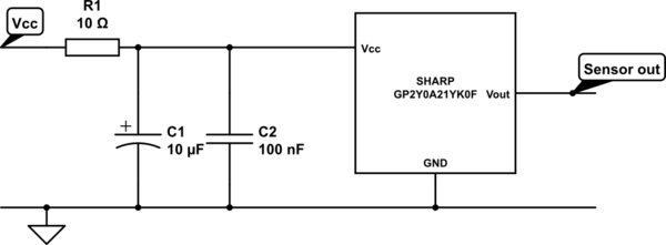
A project involves two distance sensors that signal an Arduino to operate a servo motor when an object comes within range. The system functions correctly; however, the sensors output a consistently high voltage, necessitating a high cutoff voltage in...
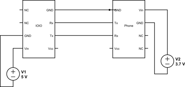
This project utilizes Sparkfun's IOIO for Android, focusing on power consumption concerns. The IOIO board can provide the phone with 500 mA charging, which may be excessive for continuous operation. The proposed solution is to power both the phone...