
Audio Clipping Detector Circuit
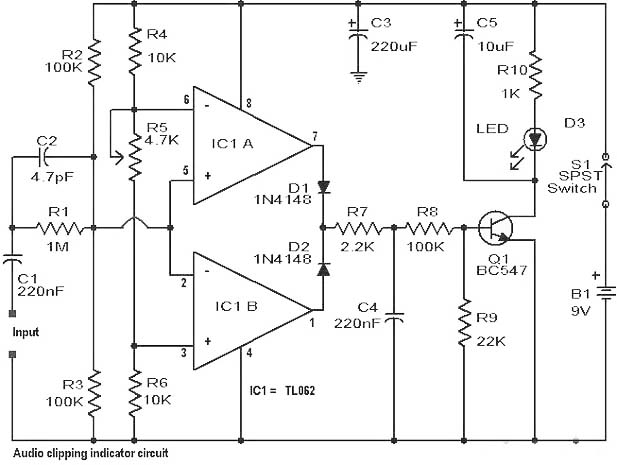
The clipping detection circuit operates by leveraging the principles of signal comparison through the use of operational amplifiers configured as window comparators. The TL082 operational amplifiers are chosen for their low noise and high precision characteristics, making them suitable for audio applications where signal integrity is paramount.
The input signal enters the circuit and is fed into the non-inverting and inverting inputs of the operational amplifiers. The circuit is designed to monitor both the positive and negative peaks of the waveform. When the input signal exceeds the predefined thresholds set by the potentiometers R1 and R5, the operational amplifiers output a high signal, triggering the subsequent components in the circuit.
Diodes D1 and D2 play a crucial role in ensuring that the signal driving transistor Q1 is appropriately conditioned. They rectify the output from the operational amplifiers, allowing only the necessary signal to pass through to activate the transistor. Transistor Q1 functions as a switch, controlling the current flow to the LED. When the transistor is activated, the LED lights up, providing a visual indication of clipping in the waveform.
The inclusion of capacitor C5 introduces a delay in the circuit, which is essential for distinguishing between transient peaks and sustained clipping signals. This feature allows the circuit to respond accurately to rapid changes in the waveform without false triggering.
The entire circuit is powered by a 9-volt battery, ensuring portability and ease of use in various settings, including live sound reinforcement and studio environments. The circuit's versatility makes it an invaluable tool for audio engineers and technicians, as it can be employed with a wide range of audio equipment, such as power amplifiers, pre-amplifiers, and mixers, enhancing the overall audio quality by providing a means to monitor and address clipping issues effectively.Clipping is one of the main problems that causes distortion in amplifiers. It causes the amplitude level of a waveform to drop suddenly before it reaches the limit that it was supposed to reach. Well, here is a simple circuit that will help to detect the clipping in a waveform. The clipping can be identified as an LED is kept as the alert indicato r when a clipping occours. This circuit will show correct accuracy if you are able to make it on a high quality PCB. The circuit is mainly based on the working of two operational amplifers (TL 082) inside IC1. They act as window comparators. All it does is to detect the input signal and find out its positive or negative peak value. Correct calibration of the circuit can be done with the POT R5, while POT R1 has to be adjusted to the level at which the LED is supposed to glow. As we can see Diodes D1 and D2 are connected to the output of the operational amplifier. They are used to drive the transistor Q1 which further drives the LED to glow. A very small time delay is induced by the capacitor C5 so as to identify rapid as well as short peaks.
The circuit will easily work with the help of a 9 Volt battery. The circuit is very useful and can be used on all types of power amplifiers, pre-amplifiers and mixers. 🔗 External reference
Related Circuits
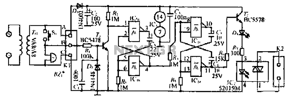
The circuit with the original m rJ bamboo is designed similarly. It includes a secondary disk that functions as a floodlight. A grass-flow filter is incorporated for a light input. An electric connection is established with a door button...
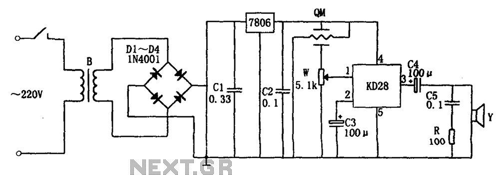
The system includes a gas-sensitive sensor element QM (type QM-N5), a buck rectifier, and regulator circuits, integrated circuits KD28, a speaker Y, and other components. The buck regulator circuit features a transformer rectifier and a bridge rectifier comprising diodes...
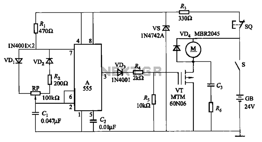
The adjustment potentiometer (RP) allows for modification of the duty cycle of a square wave generated by the 555 integrated circuit (IC) in New Zealand, enabling control of motor speed within a range of 0 to 100%. The circuit utilizes...

When building a lead-acid battery charger for a 6V or 12V battery, there are various methods available. One preferred option is the use of the IC LM317. The LM317 is a versatile adjustable voltage regulator that can be effectively utilized...

An air bridge after the bullock Phi Beach in Sichuan utilizes direct beam lights. Control is implemented for six buildings with filtered output at specific voltage levels. The system includes a small 4H servant for pressure control, and components...

This circuit prevents surges caused by power failures or interruptions, protecting electrical appliances from damage. It automatically switches to a short circuit mode when necessary. The surge protection circuit is designed to safeguard sensitive electronic devices from voltage spikes that...