
A deaf visual doorbell circuit

The circuit described includes several key components that work together to create a functional doorbell system. The initial stage involves the activation of a door button (S1), which serves as the user interface for triggering the doorbell. Upon pressing the button, a signal is sent to a monostable multivibrator circuit, which generates a precise output pulse. This pulse duration is critical, set at 15 milliseconds, allowing for a stable operation of the subsequent components.
The RF tube (Tl) operates at a frequency of 5011z, which is essential for the wireless transmission and reception of the doorbell signal. The semiconductor (Si) plays a pivotal role in switching the circuit states, enabling the RF tube to turn on and off as required by the system's operation.
A light-emitting diode (LED) is integrated into the circuit as an indicator, illuminating in response to the doorbell activation. The LED is connected in series with a bulb to provide visual feedback when the doorbell is pressed. This configuration ensures that the user can easily identify when the doorbell is active.
The circuit's power requirements are approximately 10W, which is sufficient to drive the light and the RF components effectively. Additionally, the design includes protective measures, such as diodes, to prevent back EMF and ensure stable operation. Overall, this doorbell circuit combines simplicity with functionality, making it an effective solution for signaling at entryways. Circuit with the original m rJ bamboo is also exactly the same way. Trl lose. the secondary disk sV flood-what I guanidine by day. t love grass-flow filter for a light 4Pl iU p acket road naughty electricity when connected F pity door button S1. Doorbell Ming I noon. ij this. irt, product f Bong tube Tl With 5011z rF radio frequencies title I turn on and off IE semi-conductive Si J Po, Bao and a half weeks off), which set telegraph transmission til 5 [m] llz Wklrr falling edge ici.. lC... {Single composition are more stable oscillator. After Meng monostable read by a call between a, Ma was determined to be 15 mouse monostable output pulse, the more the more it where Kai r ICl r, lcl.
l oscillator composed song, then f IlCIL meter oscillation signal output to control the drive tube T-off. r is, i Division plt Following IU is 1C. a small light-emitting diode l write off, he lost the series in the end of the mountain K2 bulb along with flash light, to ICh, IC-I, one-shot or idle time ends at prior to this release for the doorbell button + U.
send two transport tube Dll lC:. a P Wj marrow to a diode-indole step Blinking rate circuit is working properly driven bubble power. nine most a few up IOOW.
Related Circuits
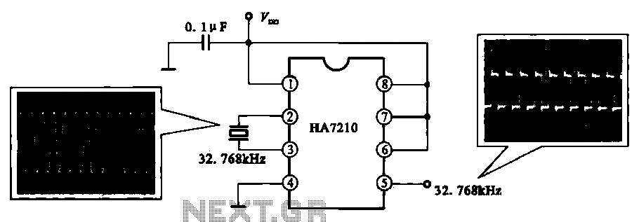
This circuit illustrates a 32.768 kHz micro-power clock oscillator, suitable for use in mobile phones, laptop computers, and home appliances. It generates a clock signal that can be utilized in various applications. The 32.768 kHz micro-power clock oscillator circuit is...

This design circuit is for audio graphic equalizers, which are commonly found as commercial products, yet published circuits for them are quite rare. The circuit features a simple design that requires an operational amplifier (op-amp) to amplify the input...

The circuit depicted in FIG. 1 generates a high-voltage signal for controlling the capacitance of barium strontium titanate (BST) capacitors. By applying voltages of V and 3V to the appropriate terminals, the capacitance of the BST can be modified....

This light chaser circuit, which functions as a music-operated lighting effect generator, consists of five sets of 60W bulbs arranged in a zig-zag configuration. The light chaser circuit is designed to create dynamic lighting effects that synchronize with music, enhancing...
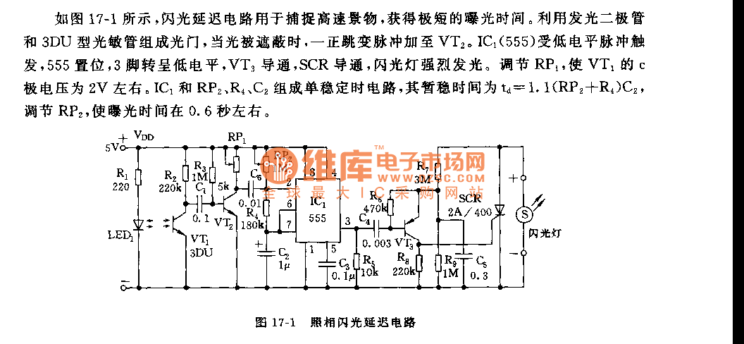
As shown in figure 17-1, the camera flash delay circuit is designed to capture high-speed scenes, allowing for very short exposure times. The light gate consists of a luminous diode and a 3DU type photosensitive tube. When the light...

This is a 50-watt audio power amplifier circuit based on the single IC STK4036II. A heatsink is required to prevent overheating of the IC. The amplifier circuit provides good sound quality at an affordable price and is easy to...