
Variable speed electric motor bike circuit

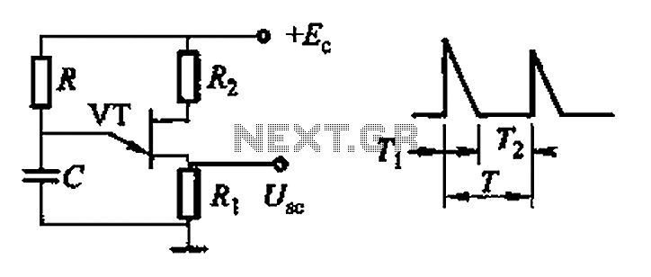
The circuit utilizes a 555 timer IC configured in astable mode to produce a square wave output. The adjustment potentiometer (RP) is integrated into the timing circuit, influencing the charge and discharge times of the timing capacitor. By varying the resistance of the potentiometer, the duty cycle of the square wave can be adjusted, which directly affects the average voltage supplied to the motor.
In this configuration, the 555 timer operates with two resistors (R1 and R2) and a timing capacitor (C). The values of R1 and R2 are fixed, while RP is variable. The duty cycle (D) of the output waveform can be calculated using the formula:
D = (R2 / (R1 + 2 * R2)) * 100%
As RP is adjusted, the ratio of R2 to the total resistance (R1 + R2) changes, thereby altering the duty cycle. This change in duty cycle results in a corresponding change in the effective voltage applied to the motor, allowing for precise speed control. The motor can operate from a complete stop (0% speed) to full speed (100%) depending on the position of the potentiometer.
The circuit should include additional components such as a diode for back EMF protection and possibly a transistor or MOSFET to handle higher current loads required by the motor. Proper decoupling capacitors should also be placed near the power supply pins of the 555 IC to ensure stable operation. This design provides a simple yet effective method for controlling motor speed using a widely available 555 timer IC.Adjustment potentiometer RP, can change by the 555 IC A New Zealand into a square wave duty cycle of the square wave, the motor speed to achieve the purpose of the speed range of O-l00%.
Related Circuits

The Univibe is a footpedal-operated phaser or phase shifter designed to generate chorus and vibrato simulations for electric organs or guitars. It was introduced in the 1960s by Shin-ei, with the intention of emulating the "Doppler sound" characteristic of...
Common non-sinusoidal oscillator circuit, waveform and frequency formula - pulse wave oscillator - blocking oscillator transformer The common non-sinusoidal oscillator circuit is designed to generate pulse waveforms, which are characterized by their square or rectangular shape. These oscillators are...
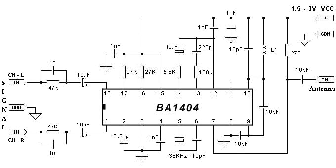
The BA1404 FM stereo modulator IC includes all the necessary components to design a simple, high-efficiency stereo transmitter circuit. It features a stereo modulator that generates composite stereo signals, an FM modulator for creating FM signals, and an RF...
This circuit is designed to demonstrate high frequency and high voltage, capable of producing approximately 30kV, depending on the transformer utilized. It is cost-effective and straightforward to construct, primarily using a standard TV flyback transformer. This circuit can power...
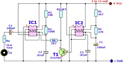
Browse home alarm circuit explanation latest schematic siren wailing with latest Wailing Alarm Siren circuit schematic with explanation. The loudspeaker LS and the resistor marked Rx should be together 75 ohms. If a standard 8-ohm speaker is used, then...
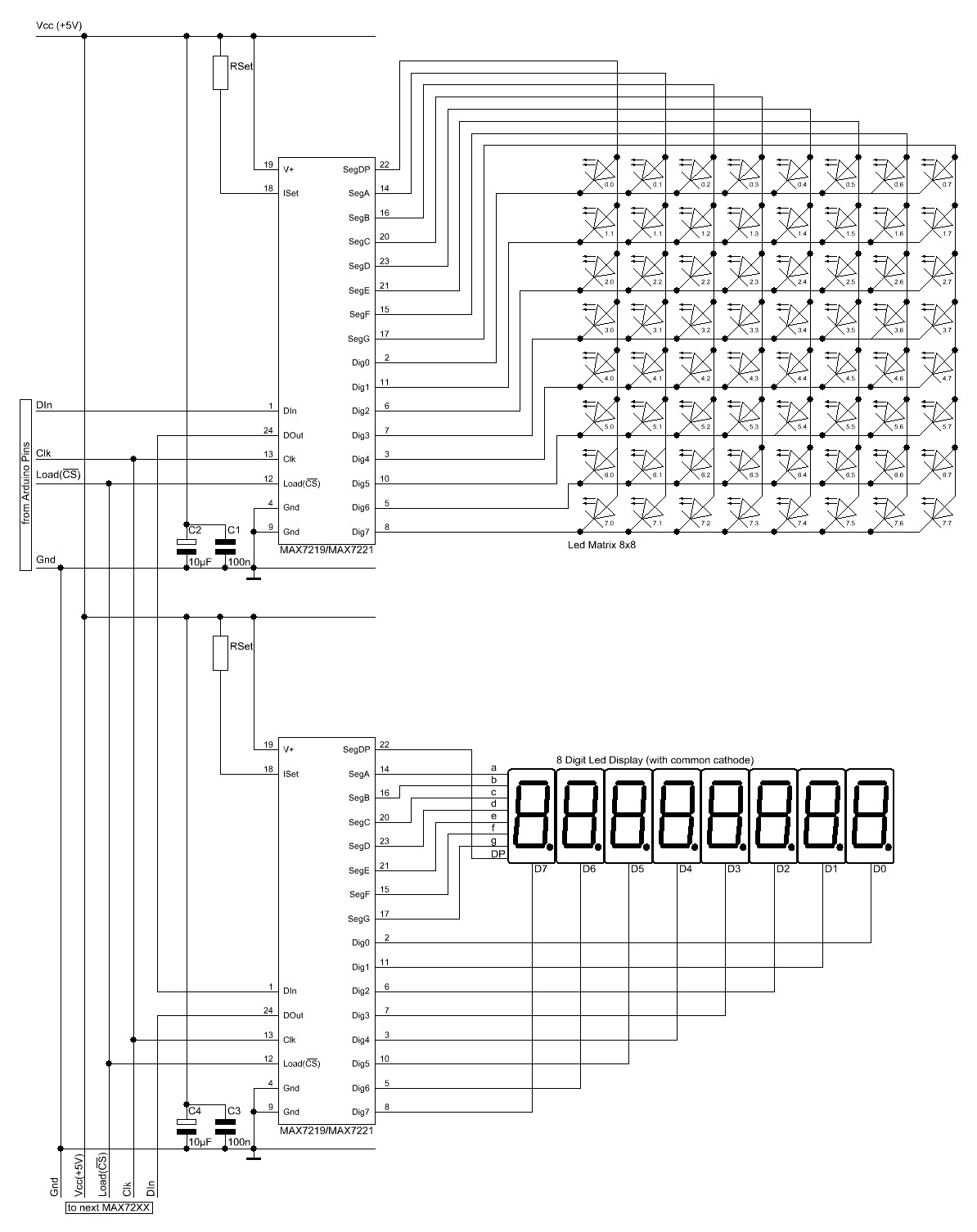
The Arduino website provides comprehensive documentation on connecting LEDs to the Arduino using the MAX7221. A specific set of components is required for this setup. The MAX7221 is a versatile LED driver that enables the control of multiple LEDs through...