
Audio Distortion Meter Circuit with Diagram
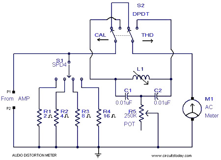
The audio distortion meter is structured around a notch filter configuration that effectively isolates the fundamental frequency while attenuating harmonic frequencies. The selection of load impedance is facilitated through a switch or jumper settings that connect the appropriate resistive load to the circuit. The notch filter, composed of an inductor (L1) and capacitors (C1 and C2) in conjunction with a resistor (R1), is designed to create a deep attenuation at the 1 kHz frequency. This allows for precise measurement of the THD by comparing the output signal to the input signal.
To implement the circuit, the 1 kHz signal can be generated either by a dedicated signal generator or by constructing a Colpitts oscillator, which utilizes a combination of capacitors and an inductor to produce a stable sine wave output at the desired frequency. The oscillator circuit typically includes a transistor configured in a feedback loop to ensure consistent oscillation.
Once the input signal is fed into the amplifier under test, the output can be connected to a measurement device, such as an oscilloscope or a spectrum analyzer, to analyze the distortion characteristics. The difference between the fundamental frequency and the harmonics will provide a quantitative measure of the THD, which can be calculated using the ratio of the power of the harmonics to the power of the fundamental frequency. This process enables engineers and technicians to evaluate the performance of audio amplifiers and ensure that they meet the required specifications for audio fidelity.Here is a simple 1KHz audio distortion meter that can measure the Total Harmonic Distortion (THD) on any load at any out put power. Here you have the option to select 2, 4, 8 or 16 Ohm loads. The circuit works by filtering the 1 kHz fundamental signal using a notch filter comprising of L1, C2, C1, R1.
With a little time and calculation you can get the c orrect THD of your amplifier in such a simple way. Feed the input of your amplifier a 1KHz signal from a signal generator. If you don`t have a signal generator make a 1 kHz Colpitts oscillator for the purpose. 🔗 External reference
Related Circuits
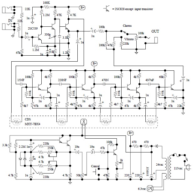
The Univibe is a footpedal-operated phaser or phase shifter designed to generate chorus and vibrato simulations for electric organs or guitars. It was introduced in the 1960s by Shin-ei, with the intention of emulating the "Doppler sound" characteristic of...
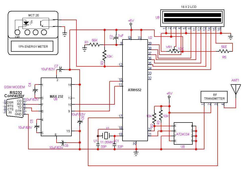
GSM based Automatic meter reading, or AMR, is the technology of automatically collecting data from energy meter and transferring that data to a central database for billing and/or analyzing. The Transmitter is connected to the meter and it counts...
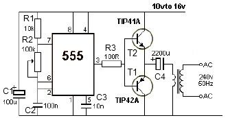
This 12V power inverter circuit can be utilized to power small devices that require 240 volts. It is particularly advantageous for operating 240-volt appliances using a 12-volt car battery. Unlike typical feedback oscillator inverters, this design employs a 555...
This circuit utilizes the TLC555CP timer integrated circuit to flash an LED approximately twice per second. This specific 555 timer operates on a voltage of only 3 volts, allowing it to be powered by two 1.5-volt cells. When using...
This power supply is designed for amateur use and has been operational for over 10 years. Its design is straightforward and largely resistant to radio frequency interference (RF). The system incorporates various components, with the most significant being a...
The circuit diagram illustrates a five-use tri-state audio logic pen utilizing components such as the CD4066 and a 555 timer. The primary elements include a multivibrator, a four-way switch (CD4066, designated as IC1), and a gate circuit formed by...