
Automatic Air Humidifier

The humidifier circuit utilizes a humidity sensor (Type NH-3) to monitor environmental moisture levels and control a ventilator for air humidification. The system is powered by the mains supply, which is transformed into lower DC voltages suitable for sensor operation. The circuit includes essential components such as capacitors, resistors, zener diodes, and a triac, all working together to create a reliable and efficient humidification mechanism.
The conversion of 240 V AC to 8.9 V pulsating DC is critical for powering the sensor and supporting the circuit's functionality. The design incorporates a bandpass filter to ensure that the sensor receives a stable alternating voltage, which is essential for accurate humidity detection. The op amp (IC2) plays a crucial role in processing the sensor's output, providing a control signal that regulates the triac, thus controlling the ventilator's operation based on humidity levels.
The feedback mechanism through hysteresis ensures that the system operates effectively without rapid on-off cycling, enhancing the overall stability of the humidification process. The inclusion of discharge paths for capacitors after power-off is a safety feature, preventing any residual voltage that could pose a hazard during maintenance or operation.
Overall, this circuit design exemplifies a practical approach to humidity control in an air humidifying system, with considerations for safety, component selection, and operational efficiency.The humidifier circuit is based on a special humidity sensor Type NH-3 from Figaro. Depending on the sensor output, the circuit drives a ventilator that is part of an air humidifying installation. The ventilator is switched on an off by a triac. So as to keep the circuit as simple as possible, the supply voltage and the test voltage are drawn dire
ctly from the mains supply. The 240 V mains voltage is converted into an 8. 9 V pulsating direct potential by capacitor C1, resistor R1 and zener diode D1. The pulsating voltage is used to drive the sensor. It is also transformed to a 7. 5 V supply voltage by D2 and C2. The sensor needs an alternating drive voltage at a level not higher than 1. 5 V. This potential is obtained from the pulsating direct voltage by network R2-R3-C3-C4, which removes the direct voltage component and lowers the level to 1. 4 V. At the same time, the network functions as a 50 Hz bandpass filter. To ensure that the drive voltage for the sensor does not fall outside the common-mode range of op amp IC2, an offset potential of 3.
9 V is applied to the sensor as well as to the voltage reference source of the op amp. This potential is provided by zener diode D3. The reference level is set with P1. The op amp is given some hysteresis by R5. When the humidity of the ambient air rises above that corresponding to the level with P1, the output voltage of IC2 is about 6 V. This results in T1 being cut off by D4, whereupon the triac is also disabled. When the humidity drops below that corresponding to the level set with P1, a pulsating potential appears at the output of IC2.
This voltage is used to charge capacitor C6. The charged capacitor thereupon provides a steady current to the triac. When T1 is cut off for some time, capacitor C6 is discharged via resistor R7. Capacitors C1 and C7 are discharged via R9, so that after the mains has been switched off, no dangerous potential remains at the pins of the mains connector (K1). The humidifier is best built on the PCB shown in Figure 2, which is available ready made (see Readers services pages towards the end of this issue).
Bear in mind that parts of the board will carry mains voltage, which makes careful working and the enclosing of the board in a plastic case imperative. The humidifier may be converted into a dehumidifier by interchanging connections 1 and 3 to sensor IC1.
🔗 External reference
Related Circuits

When the ignition switch is activated, relay K1 receives continuous power, allowing the headlights to be turned on. When the ignition is turned off, timer IC1 is activated, maintaining its power for a duration determined by resistor R1 and...
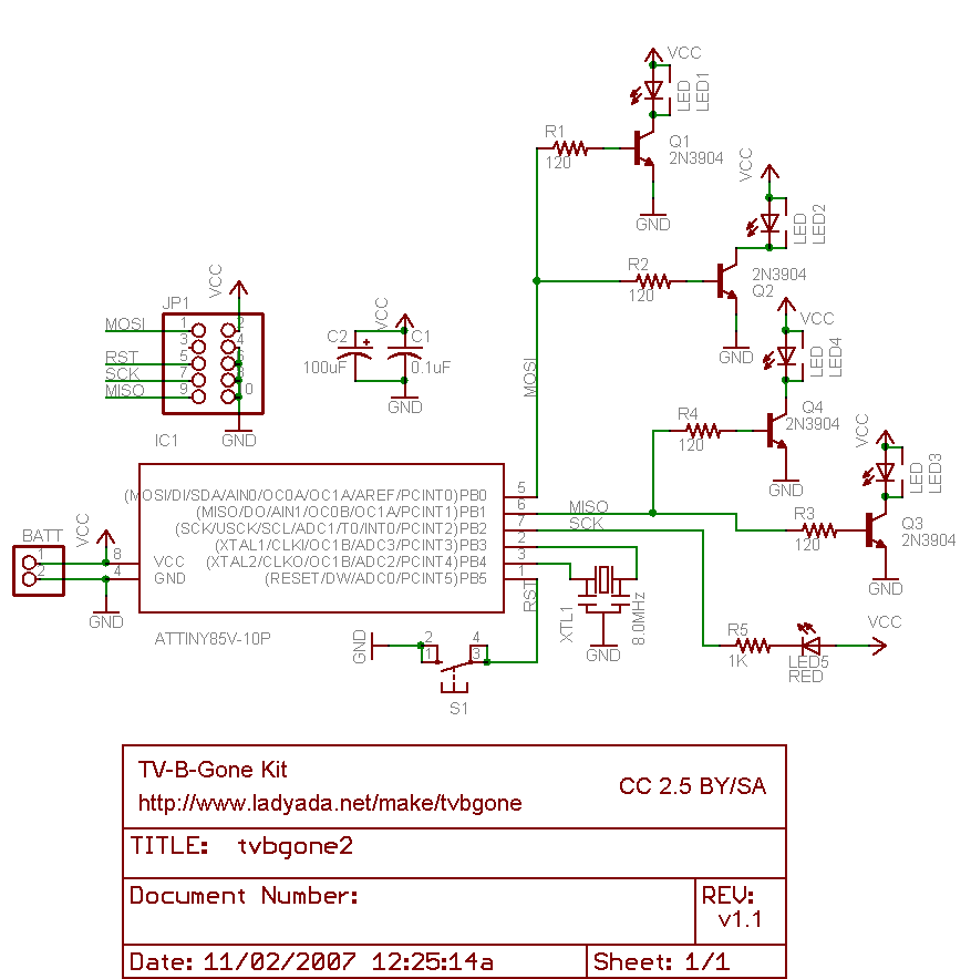
Why use one resistor and one transistor for each LED instead of connecting the LEDs in series and controlling them with a single transistor? This approach is controlled by an Arduino pin through a single resistor. While there is...
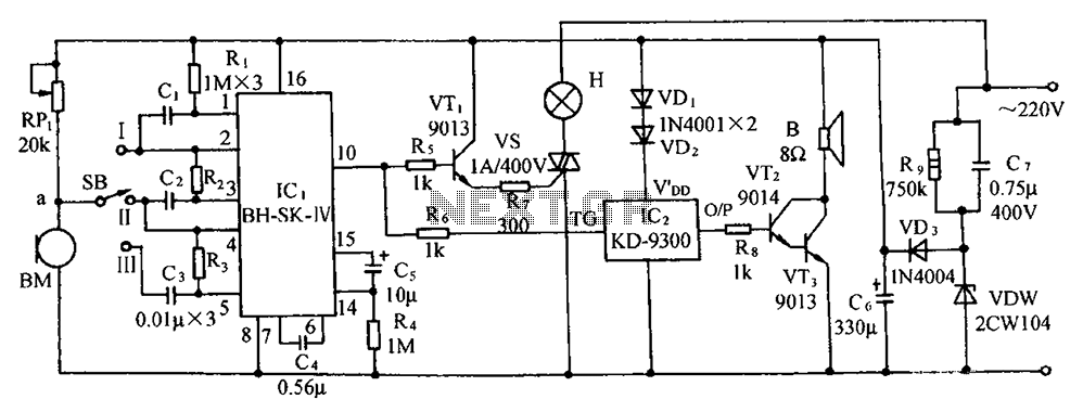
The circuit includes a microphone transducer, voice circuits, an SCR control circuit, a vocal music buck rectifier circuit, and an AC circuit. The BH-SK-IV serves as the core of the device. The described circuit is a complex assembly designed to...
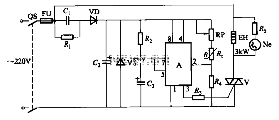
An automatic temperature control circuit is designed for climate control thermostats. Its primary function is to maintain a constant internal temperature using an electric heater (EH). The control mechanism utilizes a negative temperature coefficient thermistor as the temperature sensing...
The circuit depicted will automatically switch ON and OFF at night and morning, respectively. In this circuit, R1 can be adjusted to change the sensitivity. The operation of the circuit is straightforward. The Light Dependent Resistor (LDR) exhibits very...
This straightforward circuit can be integrated into a headlight switch to enable automatic switching between high and low beam headlights when there is oncoming traffic. It is a simple electronics project accompanied by a circuit diagram. The circuit operates by...