
Bicolour LED flasher circuit

The described circuit employs the widely used 555 timer IC configured in astable mode, which allows it to produce a continuous square wave output. The configuration includes a timing resistor connected to pin 7 (discharge) and a timing capacitor connected to pin 6 (threshold), which together determine the frequency of the output signal. The output at pin 3 alternates between high and low states, controlling the activation of the LEDs.
In this specific design, the bi-color LEDs are arranged in a manner that enhances the visual effect. When the output from the 555 timer is high, one color of the LEDs illuminates, while the PNP transistor BC558 is triggered to allow the other color to flash when the output is low. This arrangement creates a visually appealing alternation between colors.
The inclusion of a 100K variable resistor (VR1) allows for adjustment of the blinking rate, providing flexibility in the timing of the LED flashes. The absence of current-limiting resistors simplifies the circuit but introduces a risk of unequal brightness between the red and green LEDs. Each LED type has a different forward voltage drop, which can lead to one color appearing brighter than the other during operation.
Overall, this circuit is an effective and simple design for creating an eye-catching LED flashing effect, suitable for decorative lighting or signaling applications. The use of the 555 timer ensures reliability and ease of implementation, making it accessible for hobbyists and educators alike.Basically this circuit is similar to some flasher circuits already published in using IC555 as a free running multivibrator. The only difference lies in the way it flash using bi-colour LEDs. When output at pin 3 of IC 555 goes high it operates on group of LEDs. By inverting the IC`s low output by pnp transistor BC558 the other group of LEDs is m ade to flash. AS shown in circuit diagram the LEDs are arranged in alternately reversed order so that a twinkle twinkle little stars effect is produced. The 100K preset VR1 sets the blinking rate. To maintain simplicity I omitted the current limiting resistor. So, the red and green LEDs may not flash with equal intensity (as they require different threshold voltage).
🔗 External reference
Related Circuits
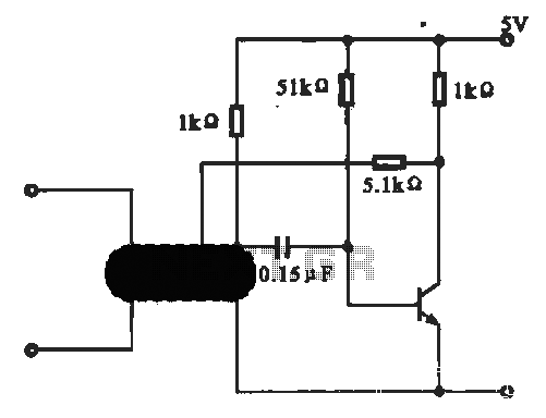
This circuit illustrates an oscillator that is controlled by an optocoupler, utilizing photoelectric coupling to drive a transistor. The oscillator circuit described operates by employing an optocoupler to provide electrical isolation between its input and output stages while allowing control...

When the sensor detects movement in a room it will take a burst of 10 photos with the digital camera. Each photo is taken at 0.5sec interval. After the 10 photos, the camera waits 3 seconds for further movement...

The circuit illustrated in Figure 3-73 is designed to utilize the power generated by instantaneous power failures, specifically the self-induced electromotive force (emf) produced by the motor, to implement an immediate shutdown protection mechanism. During a momentary power outage,...
The circuit below demonstrates how to power one or two LEDs from a 120-volt AC line. It utilizes a capacitor to reduce the voltage and a small resistor to limit the inrush current. As the capacitor needs to allow...
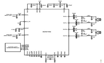
This is a typical stereo application circuit schematic of the ADAU1592, a 2-channel, bridge-tied load (BTL) switching audio power amplifier. The ADAU1592 can be utilized in flat panel televisions, PC audio systems, and mini-component applications. The ADAU1592 is designed to...

This document presents a principle circuit for electronic games. The main circuit operates in conjunction with the host through the reset button SB2, while the indicators VD1A-VD9A remain off. Prizes, for example, five, are determined by the number of...