
Burglar Alarm Circuit with Diagram

The burglar alarm circuit is designed to provide a basic security solution for residential or commercial properties. The circuit typically consists of a few essential components: a power source, a sensor, a triggering mechanism, and an output alert system.
The power source, usually a battery or a DC power supply, provides the necessary voltage to operate the circuit. The sensor, which can be a simple switch or a more sophisticated device such as a magnetic reed switch, detects unauthorized access. This sensor is often installed on windows or doors, where it can be activated by the opening or breaking of the seal.
When the sensor is triggered, it completes the circuit, allowing current to flow to the triggering mechanism, which may include a relay or a transistor. This component amplifies the signal and activates the output alert system, which can be a loud siren, a flashing light, or even a notification system that alerts the property owner via a mobile device.
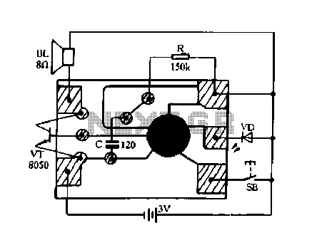
For installation, the burglar alarm circuit should be connected to a window foil, which acts as a conductive path. If the window is tampered with, the foil breaks the circuit, triggering the alarm. This simple yet effective method helps deter potential intruders and enhances the overall security of the premises.
The schematic representation of this circuit typically includes symbols for each component, clearly indicating their connections and functionality. Proper attention to component ratings and circuit layout is essential for ensuring reliable operation and minimizing false alarms.A simple burglar alarm circuit diagram and schematic. This can be used as anti theft alarm by attaching the burglar alarm circuit to window foil.. 🔗 External reference
Related Circuits
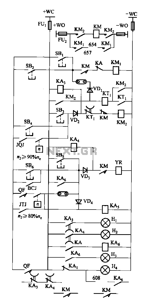
The FKL-32 type automatic thyristor excitation device is designed for synchronous generators with a terminal voltage of 400V and a capacity of 500kW and below. It is used for the automatic adjustment of excitation. The FKL-32 thyristor excitation device is...
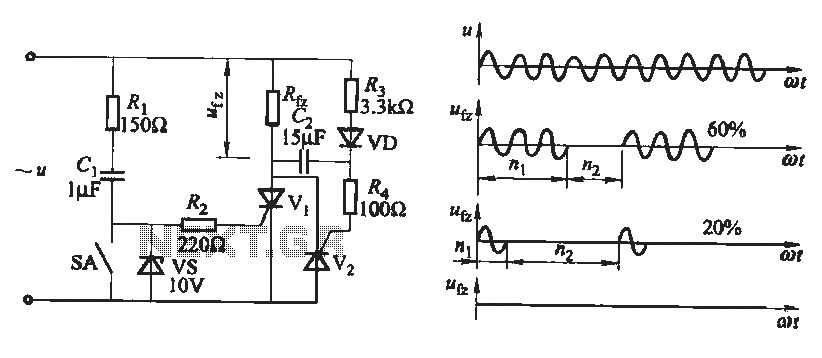
The output waveform of the thyristor zero trigger circuit is a sine wave, which does not generate electromagnetic interference like a phase-shift trigger circuit. This circuit serves as a basic thyristor power adjustment mechanism. In the circuit diagram, the...
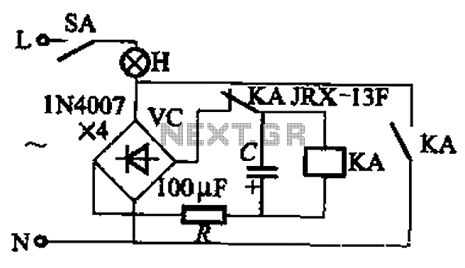
The circuit illustrated in Figure 13-3 consists of two configurations: (a) a DC power supply and (b) an AC power supply. Both configurations are utilized to control a relay. The flash frequency of the relay is determined by the...
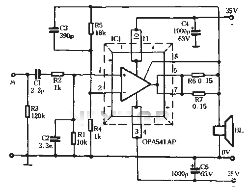
The Burr-Brown OPA541 chip is a power amplifier capable of operating with a maximum power supply voltage of 40V, delivering a continuous output current of up to 5A. The output current can be adjusted using an external resistor to...

The circuit consists of a 555 timer IC configured as a multivibrator, which operates with two probes to measure the water level. When the capacitance between the probes indicates a high water level, the output from the 555 timer...
Constantly changing light and sound analog controller circuit 02 The circuit described is an analog controller designed to modulate light and sound in a dynamic manner. It typically utilizes components such as operational amplifiers, resistors, capacitors, and transistors to achieve...