
Blinker circuit one b

The circuit in Figure 13-3 demonstrates two distinct power supply options for relay control, which can be essential in various electronic applications. The first configuration, featuring a DC power supply, typically provides a stable voltage that can be easily regulated. This stability is crucial for applications where precise timing and control are necessary, as it ensures consistent relay operation without fluctuations.
In contrast, the second configuration employs an AC power supply, which introduces a different set of characteristics. AC power can be advantageous for certain relay types, especially those designed to operate with alternating current. The relay's activation in this scenario is influenced by the AC frequency, which can affect the timing and duration of the relay's operation.
The flash frequency of the relay is a critical parameter that defines how frequently the relay can switch on and off. This frequency is determined by the combination of resistance and capacitance in the circuit. The resistance (R) limits the current flowing through the circuit, while the capacitance (C) stores energy and influences the timing of the relay's activation. The relationship between these components can be expressed through the time constant τ (tau), which is calculated as τ = R × C. A higher resistance or capacitance results in a longer time constant, thus reducing the flash frequency. Conversely, lower values of R or C will increase the flash frequency, allowing the relay to operate more rapidly.
In practical applications, selecting the appropriate values for resistance and capacitance is essential to achieve the desired relay performance. The relay KA capacity must also be considered, as it indicates the maximum load the relay can handle without failure. This ensures that the relay operates within its specified limits, providing reliable performance in the intended application. Circuit shown in Figure 13-3. Figure 13-3 (a) DC power supply, Figure 13-3 (b) with AC power. They are used to control the relay. Flash frequency is determined by the resistanc e and capacitance C relay KA capacity.
Related Circuits
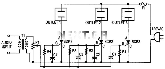
The AC line power is introduced into the circuit through F1, a protective 5-A fuse. One side of the AC line is connected to one side of each AC outlet, while the other side is connected to each silicon-controlled...
The amplifier is capable of delivering around 1.5W into 8 ohm headphones, and 2.2W into 32 ohms - this is vastly more than will ever be needed in practice. The use of a 120 Ohm output resistor is recommended,...
It is well known that pests like rats, mice, etc., are repelled by ultrasonic frequency in the range of 30 kHz to 50 kHz. Human beings can't hear these high-frequency sounds. Unfortunately, all pests do not react at the...
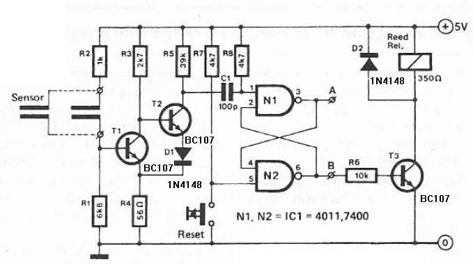
Humidity detector circuit electronic project using common electronic parts The humidity detector circuit is a project designed to measure and indicate the level of humidity in the environment. This circuit utilizes commonly available electronic components, making it accessible for hobbyists...
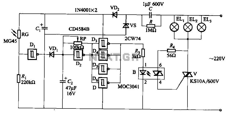
The circuit utilizes a CD4584B six Schmitt trigger integrated circuit (IC) with components Di and Ri forming a photometric circuit. D2, along with RP and C2, comprises an adjustable frequency ultra-low frequency oscillation device, where RP serves as an...

The circuit is constructed using the ICM7217 integrated circuit from Intersil, which features a CMOS up/down counter with a four-digit display. The clock generator circuit, IC3, produces a square wave clock signal with a period of one second, available...