
water level controller circuit diagram

The water level controller circuit employs a 555 timer integrated circuit (IC) configured in astable or monostable mode to monitor and regulate the water level in a tank. The two probes, positioned at different heights, serve as capacitive sensors. When the water level rises above the upper probe, the capacitance changes, signaling the 555 timer to switch its output from low to high. This transition can activate additional circuitry, such as a relay that controls a pump to maintain the desired water level.
Incorporating a decoder integrated circuit (IC3), such as the CX20106A, enhances the system's capability to process signals from infrared sensors (VD1, VD2, and VD3), which can be used for remote monitoring or control. These infrared components can be sourced as standalone units or integrated into a single module, which simplifies the design and improves reliability.
The relay in this circuit is a memory self-locking type, enabling it to maintain its state without continuous power. It requires a 20ms trigger pulse to activate and can handle substantial currents (up to 30A), making it suitable for controlling larger three-phase pump motors. This feature ensures that once the relay is engaged, it remains active until the system is intentionally reset, providing a robust solution for water level management.
Overall, this water level controller circuit is versatile and can be adapted to various applications, including irrigation systems, aquariums, and industrial water tanks. The inclusion of additional sensors and control mechanisms allows for a comprehensive automation solution that enhances operational efficiency and reliability in water management systems.It consists in 555 feet, respectively, of 1, 2-cited two-pin, using two needles with a high water level higher than 555 when the probe capacitance between 1, 2 feet circuit leaving 555 low potential output. Contrary to the output of high potential (555 composed of a standard multivibrator). For the control points up and down the water level 555 can also be used to do, good simple 3 floor Picture this subject as follows:to the file much better this time! 5th Floor Or more appropriate light or infrared sensor 6 F See ah. 7th Floor Unfortunately, not enough levels can not see ah! 8 F With a zoom control, it works in between the cut-off and saturation, thus to control a triac on and off the line, Oh 10 F Upstairs, "Lieutenant, " Hello, Can the "water level controller" information sent to my mailbox, aqiang_02318@sina.
com, thank you! ! ! ! 11th Floor No map, make Taiwan well A total of 12 topics 2 pages, current page 1 Water level controller for the water tower as shown in the circuit. The figure, IC2 available a variety of 555 integrated circuits. Decoder integrated circuit for the infrared receiver IC3 CX20106A. IC4 available 4N25, 4N26, PC817 and other optocoupler. Part of the infrared receiver infrared receiver can be purchased finished components or integrated infrared receiver can be easy to produce and improve reliability.
VD1, VD2 and VD3 use of infrared remote control transmitter and receiver diodes. J made a new selection of memory self-locking relay, relay and general appearance of the product the same, the difference is not required to maintain the current after the pull, pull and release only a certain pulse drive power is required, then the mechanical structure to maintain " locked. " The main parameters: Rated voltage 12V, trigger pulse w 20ms rectangular driving pulse, transient power consumption <0.
9W, life expectancy is 10 million times. currents 3A, 30A, etc. , can be selected. For the three-phase pump motor can be controlled through the relay or. The remaining components shown by the attention. Top articles no information about a Total User Name: Code: pdf remote wireless automatic water level controller, manual heat: pdf level controller water level control circuit principle of heat: doc level (direct) heat regulating device: pdf-type electrical level controller heat: doc tower graduate level control system Design _secret heat: pdf42 limit water level alarm device type heat: pdf estimated heat flow of water towers: doc electrode type liquid level sensor temperature: doc discrete electronic components of the tower level control system design graduate. heat: ppt digital integrated circuits input heat: xls53-towers offer automatic temperature controller: doc soft start cabinet dedicated heat pumps: doc cooled screw chiller maintenance and overhaul in order temperature heat: doc automatic control tower heat: doc pumps, water towers Control the heat: pdf Shopping Q the circuit below shows an example of simple four-stage level detector.
water level controller circuit described here control the water level inside a tank. 🔗 External reference
Related Circuits
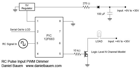
A PIC12F675 microcontroller can switch up to five outputs sequentially using a standard Remote Control pulse input ranging from 1 to 2 ms. While any RC channel input can be utilized, it is particularly effective when paired with rotary...
This sound effects circuit is designed to function as a signal distorter. When utilized with an electric guitar, it enables the creation of unique sound effects. The sound effects circuit operates by manipulating the input audio signal from the electric...
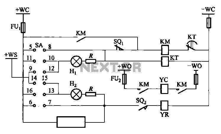
The DW10M de-excitation type switch is based on the DW10 automatic air circuit breaker, transitioning from normally open to normally closed contact. The models available include DW10M-200, DW10M-400, and DW10M-600. The control circuit for this type switch is illustrated...
Even including labor, the actual cost of purchasing, stocking, assembly, assembly errors, more expensive PCBs (with additional holes and larger sizes), and the increased difficulty in tuning would likely result in significantly higher expenses. The analysis of costs associated with...
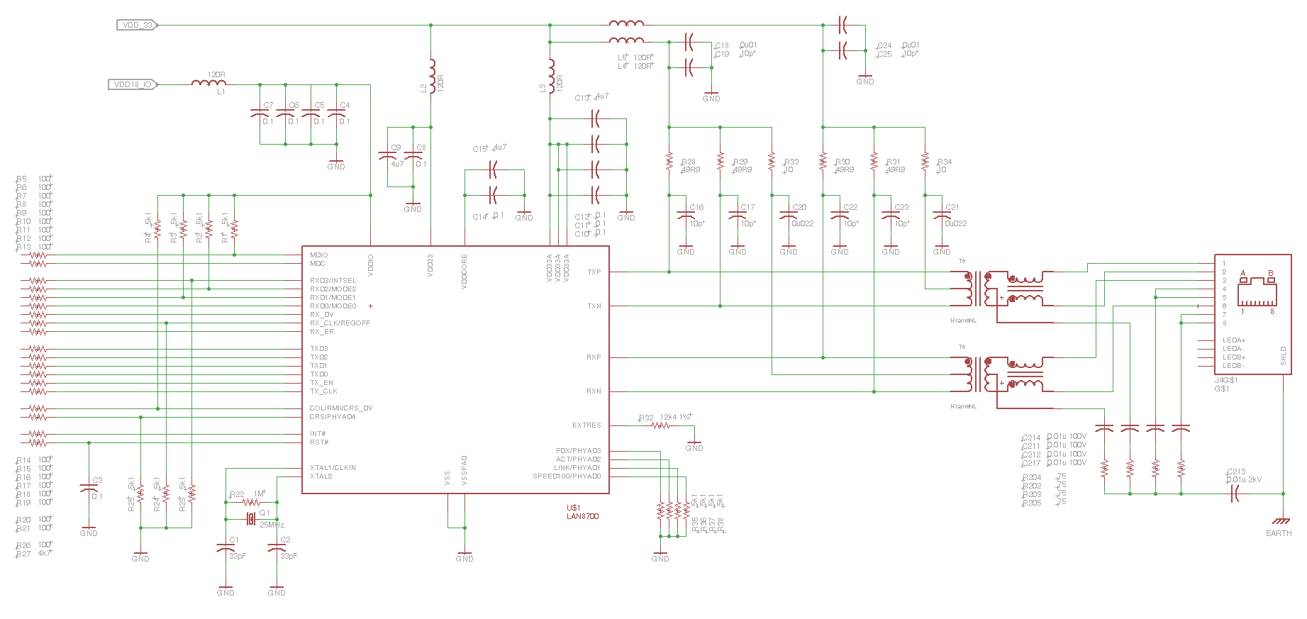
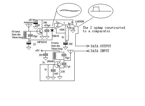
This is the eye diagram for the transmit pair. The receive pair is very similar. It is a LAN8700 PHY, and the MII interface has been effectively disabled, resulting in the PHY transmitting IDLE code sequences. It is forced...
This example describes the use of HS101 and HS201 radio transmitter and receiver modules to control rotating color lights, functioning as a multi-channel radio remote control device suitable for small dance floors or home use. Users positioned at any...