
CB 27MHz Transmitter Circuit
The 27 MHz NBFM transmitter circuit operates by employing the Motorola MC2833, a versatile chip that simplifies the design of FM transmitters. The core functionality revolves around narrow band frequency modulation, which allows for efficient use of bandwidth while maintaining audio fidelity. The transmitter is configured to operate within the 27 MHz band, commonly used for various communication applications, including hobbyist radio and short-range communications.
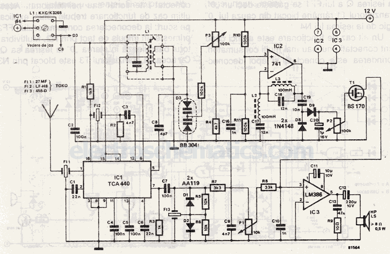
Key components of this circuit include the microphone preamplifier, where the potentiometer P1 plays a critical role in adjusting the gain to ensure that the audio signal is adequately amplified before modulation. The second potentiometer, P2, is essential for controlling the frequency deviation, which directly influences the modulation depth and audio quality transmitted.
Capacitors C9, C10, and C18 are crucial for tuning the circuit to achieve maximum output power. These components help stabilize the oscillator and filter the signal, ensuring that the transmitter operates efficiently under varying load conditions. The use of an artificial 50-ohm load during the tuning process ensures that the output power can be accurately measured, leading to optimal performance.
After adjusting the capacitors for maximum output, the circuit should be monitored using an NBFM receiver. This step is vital for ensuring that the transmitted audio signal is clear and free from distortion. Fine-tuning P1 and P2 allows for adjustments to be made in real-time, ensuring that the modulation is at its best for the intended application.
Overall, this 27 MHz NBFM transmitter circuit exemplifies a straightforward yet effective design for FM transmission, leveraging the capabilities of the MC2833 chip to deliver reliable performance in various communication scenarios.NBFM or Narrow Band Frequncy Modulation is used in this 27 MHz transmitter circuit schematic. This circuit is an application by Motorola MC2833 VHF transmitter with FM modulation and narrow band in a single chip. P1 is used to adjust microphone amplification and P2 to adjust the deviation. Remember that this 27MHz fm transmitter use NBFM withmaximum 5KHz deviation, this mean you have to use an nbfm receiver to obtain enough audio level. The transmitter is easy to adjust: trim C9, C9 and C18 for maximum output power on a artificial 50 © load. Then listen on a 27MHz radio receiver and adjust P1 and P2 untill you obtain the best modulation. 🔗 External reference
Related Circuits
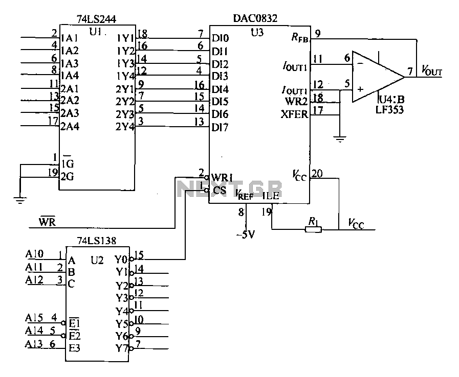
The DAC0832 is depicted in Figure 27-13 as a single-phase circuit connected to the 8086 CPU. The internal 8-bit data input of the DAC0832 must be interfaced with the CPU and the D/A converter interface circuits for data transmission,...
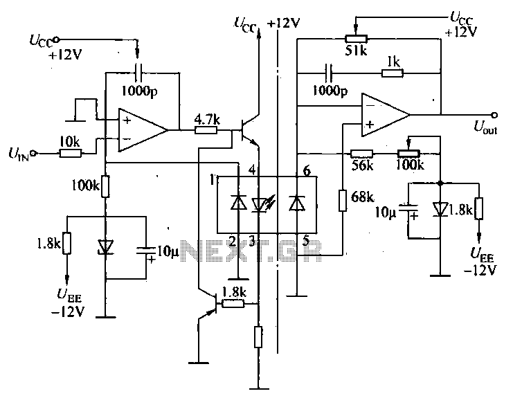
A universal optocoupler is utilized in electrocardiographs, as illustrated in Figure 5-29. Pin connections must be made carefully: the positive terminal should be connected to pin O, while the negative terminal should connect to the other pin. The control...
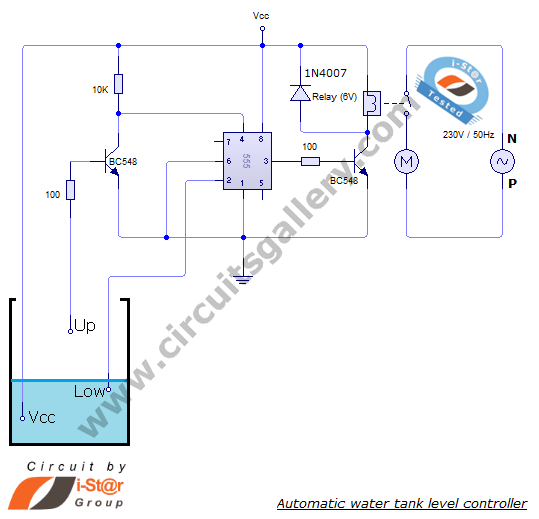
The automatic water level controller circuit is a straightforward engineering project that can automatically switch a domestic water pump on and off based on the water level in a tank. This motor driver circuit can be implemented at home...
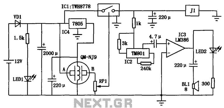
The alcohol detection alarm controller circuit is illustrated in the figure. It utilizes the QM-NJ9 alcohol gas sensor, which detects the presence of alcohol vapors. When alcohol is detected, the resistance between the AB-QM-NJ9 decreases, causing the wiper of...
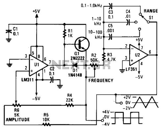
This is a simple triangle-wave generator utilizing two integrated circuit (IC) devices and a transistor. The triangle wave serves as feedback to the square-wave generator. It allows range switching across three intervals from 100 Hz to 100 kHz. Additional...
The circuit depicted will automatically switch ON and OFF at night and morning, respectively. In this circuit, R1 can be adjusted to change the sensitivity. The operation of the circuit is straightforward. The Light Dependent Resistor (LDR) exhibits very...