
Automatic water tank level controller motor driver circuit

The automatic water level controller circuit operates through a simple yet effective mechanism. The NE555 timer IC serves as the central control unit, configured in a bistable mode to manage the state of the water pump based on input from the water level sensors. The two probes installed in the tank act as sensors: the top probe detects the maximum water level, while the bottom probe detects the minimum water level. When the water level falls below the bottom probe, the circuit triggers the NE555 timer, changing its output state to high, which activates the relay. This relay, in turn, powers the water pump, allowing it to fill the tank.
As the water level rises and reaches the top probe, the circuit detects this condition and resets the NE555 timer, switching the output to low and deactivating the relay, thus turning off the water pump. This automatic regulation prevents overflow and dry running of the pump, enhancing efficiency and prolonging the lifespan of the equipment.
In terms of component selection, the NE555 timer IC is favored for its reliability and ease of use. The relay should be rated appropriately to handle the motor's current, with a 32 Ampere relay being a common choice for domestic water pumps. Additional components may include resistors and capacitors for setting the timing characteristics of the NE555 timer, as well as diodes for flyback protection across the relay coil to prevent voltage spikes.
Overall, this automatic water level controller circuit is an excellent project for demonstrating basic electronic principles and practical applications in home automation, providing an efficient solution for managing water levels in tanks.Automatic water level controller circuit is a simple engineering project. It can automatically switch ON and OFF the domestic water pump set depending on the tank water level. You can implement this motor driver circuit at your home or college using less costly components. The approximated cost of the project is about $5 only. The main advantage o f this water level controller circuit is that it automatically controls the water pump without any user interaction. The heart of this pump controller circuit is a NE 555 IC; Here we have manipulated the flip flop inside the 555 timer IC.
Our project consists of two water level sensors, one fixed at the top and other at the bottom. Working of this circuit is almost similar to a bi stable mutlivibrator. Simulation of this circuit is also given below. Definitely this will help you to do your academic project. In this project 3 wires are dipped in water tank. Let us define two water levels- Bottom (Low) level and Top (Up) level. One of the wire or probe is from Vcc. When water level goes down, the 2nd pin gets disconnected(untouched) from water i. e. voltage at the trigger pin becomes less than Vcc. Then the output of 555 becomes high. For practical implementation, you must use a relay. Rating of relay is chosen according to the load (Motor). 32 Ampere relay is best suited for domestic applications. 🔗 External reference
Related Circuits
The schematic diagram is straightforward. SW1 is a pushbutton used to start the timer. The outputs are set to logic level 0 when the timer is inactive and to logic level 1 when the timer is triggered. The relay...
This circuit is a Low-Light Level Drop Detector. It utilizes a self-biasing configuration to detect small changes in light levels. The Low-Light Level Drop Detector circuit is designed to sense minute variations in ambient light conditions, making it suitable for...
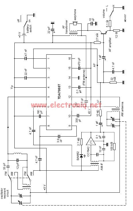
The TDA7088 incorporates a frequency-locked loop (FLL) system with an intermediate frequency (IF) of approximately 70 kHz. This circuit can be powered using a 3-volt battery cell or a regulated power supply. The TDA7088 is designed for use in various...

A GdS cell serves as one leg of a bridge circuit. Potentiometer R6 in another leg establishes the trip point. Potentiometer R5 allows for hysteresis adjustment to prevent chattering or hunting of the relay. The light level must increase...
A simple electronic lock circuit that requires minimal materials for its construction. This electronic lock circuit is designed for ease of assembly and functionality, making it suitable for various applications where secure access control is necessary. The circuit typically comprises...
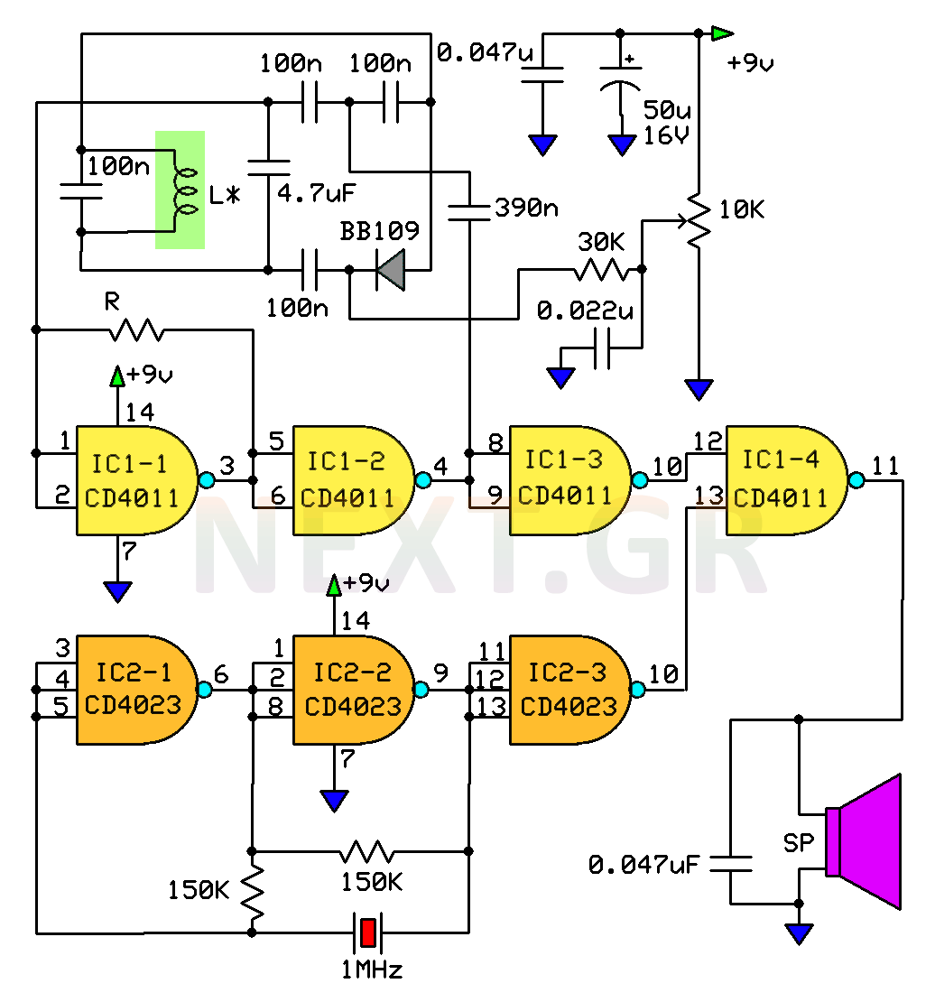
This circuit is a metal detector designed to detect large metallic objects at depths ranging from 2 to 3 meters, depending on the size of the object and the type of soil. The construction is straightforward, making it accessible...