
CIRCUIT IS NOT WORKING

The circuit in question appears to have been designed with the intention of performing a specific function, but it is currently non-operational. To troubleshoot the circuit effectively, a systematic approach is necessary.
First, a thorough inspection of the schematic diagram should be performed to ensure that all components are correctly placed and that there are no missing connections. It is essential to verify the polarity of components such as diodes and electrolytic capacitors, as incorrect orientation can lead to malfunction.
Next, measuring the voltage at various points in the circuit using a multimeter can help identify where the power is being lost. Particular attention should be given to the power supply section to confirm that it is providing the correct voltage levels. If the circuit includes integrated circuits (ICs), checking their power pins for appropriate voltage can also be crucial.
In addition, testing individual components such as resistors, capacitors, and transistors for continuity and proper values can help isolate faulty parts. For example, a resistor may have failed and is no longer providing the correct resistance, or a capacitor may have lost its capacitance.
If the circuit includes any active components, such as transistors or operational amplifiers, it may be beneficial to examine their biasing conditions. Incorrect biasing can prevent them from operating within their intended range.
Finally, if all connections and components check out, reviewing the design assumptions and operational parameters of the circuit may reveal potential design flaws or limitations that could affect functionality.
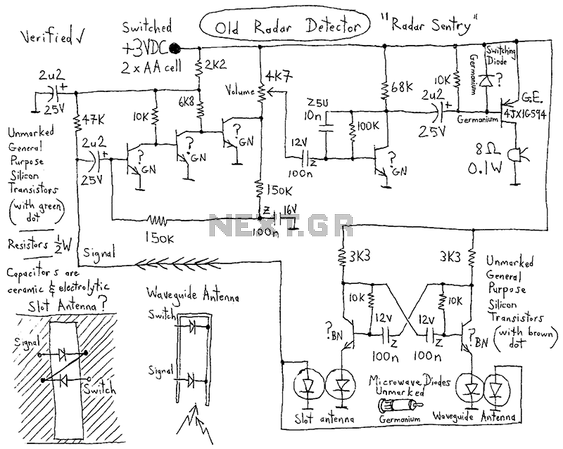
By following these steps, a comprehensive analysis of the circuit can be conducted to identify and rectify the issues preventing it from working as intended.HI ALL, PLZ LOOK THIS CIRCUIT. I BUILT THIS LAST DAY. BUT THIS IS NOT WORKING. I CHECKED ALL CONNECTIONS AND PARTS. BUT ALL IS OK. WHEN I TURN ON THE.. 🔗 External reference
Related Circuits
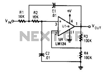
The circuit presented has a cutoff frequency of approximately 1 kHz. The resistors R1, R2, and capacitors C1, C2 can be adjusted to achieve any desired frequency. The circuit is designed as a filter, likely a low-pass or high-pass filter,...
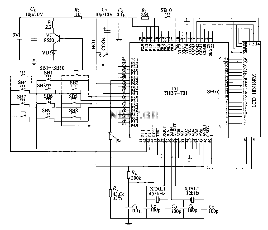
The circuit composition of a specific remote control transmitter is illustrated in a diagram. The transmitter primarily consists of a large-scale integrated circuit chip (D1, THBT-T01), a 4.5 kHz crystal oscillator, a 32 kHz crystal oscillator, a liquid crystal...
The circuit features an adjustable prestage utilizing the AF279 transistor, while the natural oscillation mixer stage employs the AF280 transistor. The power circuit is mounted on a board with copper coating. The main coil specifications are as follows: L1,...
Here is a simple circuit which can be used for decoration purposes or as an indicator. Flashing or dancing speed of LEDs can be adjusted and various dancing patterns of lights can be formed. The circuit consists of two...
Laser Command is a game developed using an 8x8 matrix LED and an Arduino Mini. It was created as a sample class project in the Gadgets, Sensors, and Activity Recognition course at Carnegie Mellon University, taught by Scott Hudson....
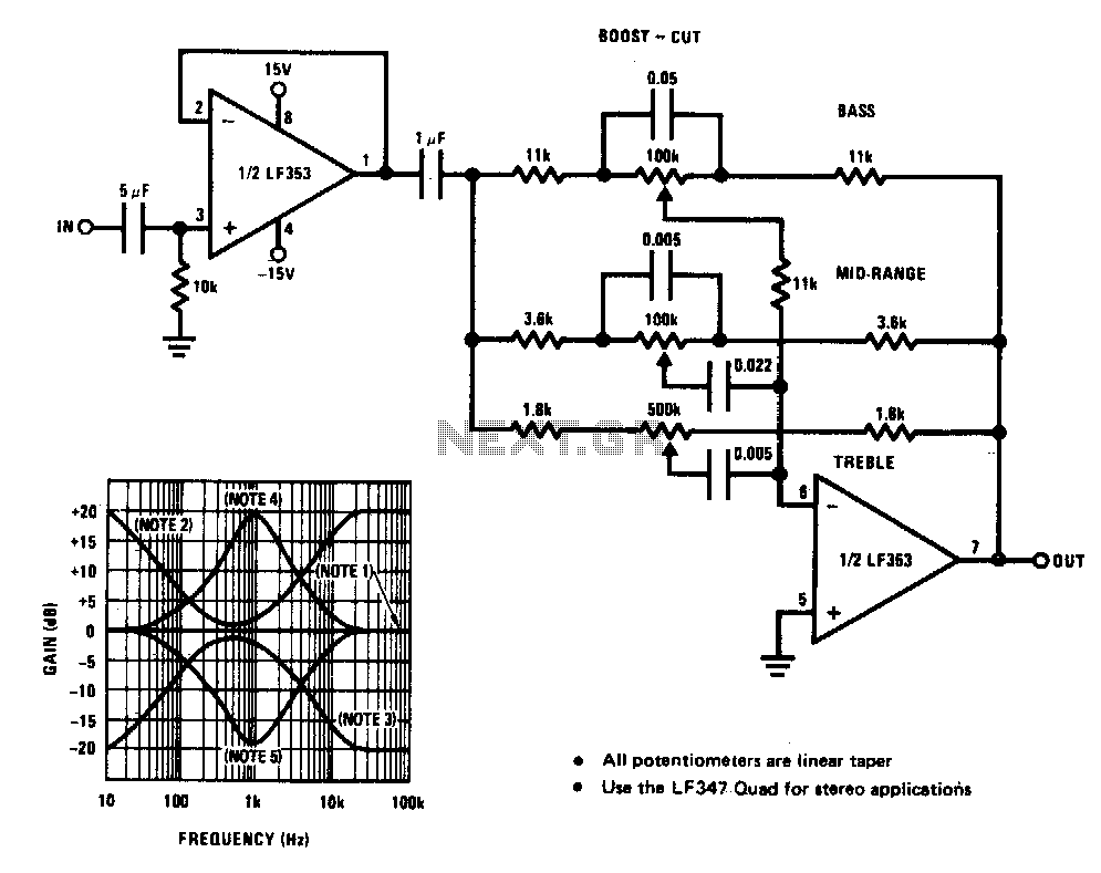
A simple single-transistor circuit provides an approximate 15 dB boost at 100 Hz and a 15 dB cut at 15 kHz. A low-noise audio transistor is utilized, and the output can be directly connected to any existing amplifier volume...