
CONTROL TONE DECODER

This circuit is designed for efficient communication in environments where multiple users may be accessing the same VHF FM repeater, thereby minimizing unnecessary noise. The tone encoder, which is unique to each user, ensures that only designated transmissions can trigger the receiver, allowing for a selective monitoring experience.
The NE567V PLL is a key component in this circuit, serving as a tone decoder that responds to specific frequencies. Its functionality is critical in distinguishing between the desired tone and other signals, thus preventing false triggering of the loudspeaker. The output from pin 8 of the NE567V is essential for controlling the state of the relay through Q2. When the correct tone is detected, the drop in voltage at pin 8 indicates that the signal is valid, leading to the activation of the relay, which connects the loudspeaker to the audio output.
The use of a relay (K1) in conjunction with the SCR (Q2) allows for a robust switching mechanism that can handle the power requirements of the loudspeaker while ensuring that it remains connected only when a valid call is received. The inclusion of a RESET switch provides a manual means to disengage the loudspeaker, ensuring that the user can quickly silence the output when needed.
The circuit's design also incorporates protection components such as the 1N4735 Zener diode (CR1), which stabilizes voltage levels and protects sensitive components from voltage spikes. The red LED (CR2) serves both as an indicator of the loudspeaker's connection status and as a visual confirmation that the system is operational.
Overall, this circuit provides a streamlined solution for personalized communication over VHF FM frequencies, enhancing the user experience by filtering out unwanted noise while ensuring that important messages are received clearly.Permits monitoring local VHF FM repeater for calls from friends without having to listen to chatter of others or to repeater noise. Operation is similar to that of Motorola paging units in which special tone is transmitted to disable squelch of receiver being called.
Each friend has tone encoder for his transmitter, set at correct frequency for co nnecting loudspeaker so desired call can be heard. Red LED comes on to confirm that loud-speaker is connected. Audio from receiver loud-speaker is fed into pin 3 of NE567V PLL U1. When correct tone frequency is received, pin 8 drops from 4V to near 0V, turning off Q1 and turning on Q2. Q2 closes relay K1, to connect loudspeaker, and holds it on until RESET switch is operated. Q2 is Radio Shack 276-1059 or other small SCR. CR1 is 1N4735, and CR2 is red LED. -K. Wyatt, Private Call System for VHF FM, Ham Radio, Sept. 1977, p 2-64. 🔗 External reference
Related Circuits
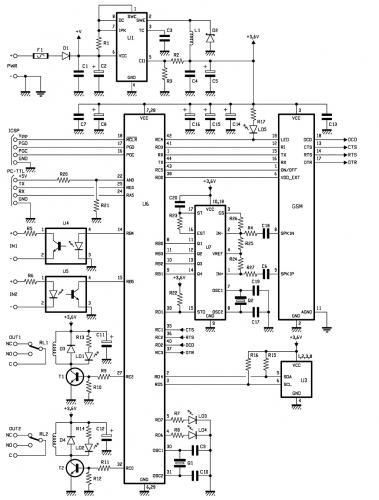
Introduction In this post, the latest application developed from the modular remote control project initiated in the April issue is presented. The modular remote control system is designed to enhance user interaction with various electronic devices through a flexible and...
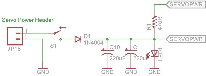
This document explains how to utilize an Arduino to control up to 12 servos simultaneously with minimal jitter. A straightforward serial interface allows for the control of the position of these 12 servo channels. Additionally, it is possible to...
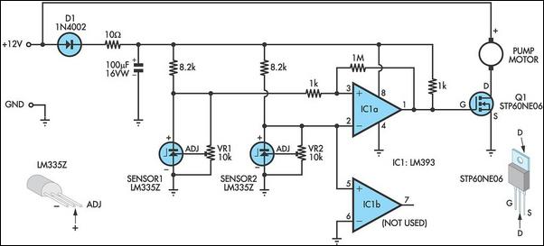
This circuit optimizes the operation of a solar hot water system. When the water in the solar collector is hotter than the storage tank, the pump runs. The circuit comprises two LM335Z temperature sensors, a comparator, and a MOSFET....
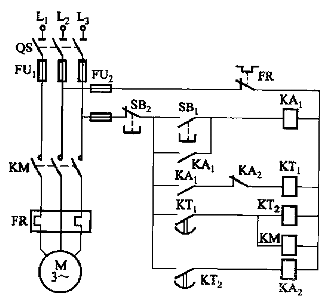
The circuit illustrated in Figure 3-76 employs two time relays, KTi and KTz, to manage the operation and downtime of a motor. The circuit utilizes two time relays to provide precise control over the motor's operational cycles. Relay KTi is...
One integrated circuit (IC) two-tone siren. It produces a double-tone police sound and a single-tone old ambulance sound. Circuit diagram components include R1 and R3, which are 470K ohm 1/4 watt resistors, and R2, which is a 680K ohm...
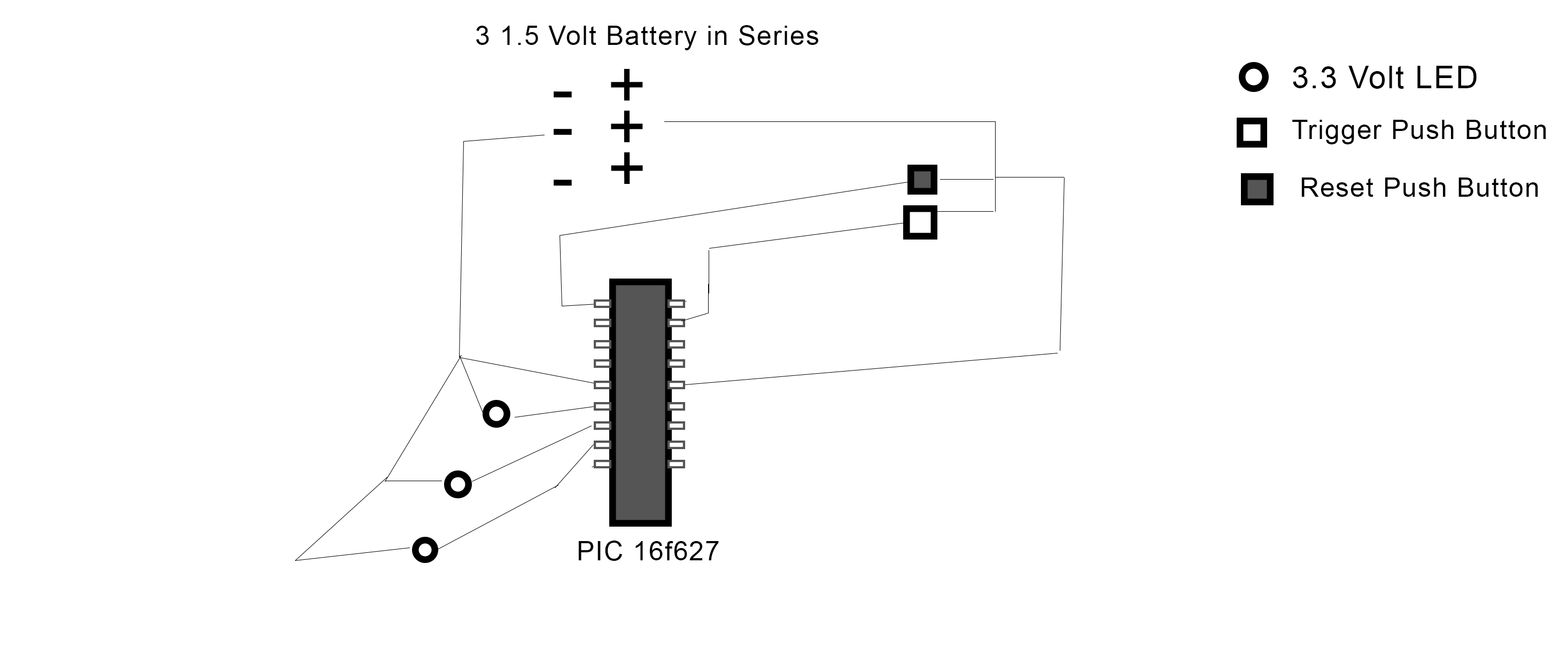
The PIC 16F627 microcontroller has been programmed to activate three LEDs when a trigger pushbutton is pressed. Additionally, when a reset pushbutton is pressed, a shutdown sequence is initiated where each LED turns off sequentially with a 5-second delay...