
One-IC two-tones Siren
The circuit is designed to generate two distinct audio tones that can be used for signaling purposes, such as in emergency vehicles. The primary component of this circuit is an integrated circuit that is capable of producing sound frequencies corresponding to the specified tones.
The two-tone police sound is typically characterized by alternating frequencies, creating a distinctive alert that is easily recognizable. In contrast, the single-tone ambulance sound provides a continuous tone that can be used in situations where a single alert is sufficient.
The resistors play a crucial role in determining the frequency of the oscillations produced by the circuit. Resistors R1 and R3, each rated at 470K ohms, are used in conjunction with R2, which is rated at 680K ohms, to set the timing intervals for the oscillation. The values of these resistors can be adjusted to modify the pitch and duration of the tones generated by the circuit, allowing for customization based on specific requirements.
In practical applications, this siren circuit can be powered by a standard DC power supply, and it may include additional components such as capacitors for filtering and smoothing the output signal. The output of the circuit can be connected to a speaker or a piezo buzzer to produce audible sound. Proper layout and connections in the circuit diagram are essential to ensure optimal performance and reliability of the siren tones.
Overall, this circuit serves as a versatile and effective solution for generating emergency alert sounds in various applications, including police cars, ambulances, and other emergency response vehicles.One-IC two-tones Siren. Double-tone Police sound. Single-tone old ambulance sound. Circuit diagram: Parts: R1,R3 470K 1/4W Resistors R2 680K 1/4W. 🔗 External reference
Related Circuits
Police siren circuit diagram. This circuit produces a sound similar to a police siren. It utilizes two 555 timer ICs. The police siren circuit typically employs two 555 timer integrated circuits (ICs) configured in astable mode to generate a square...
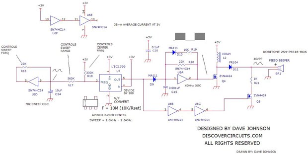
A loud sweeping siren-type audio sound generator powered by 3V. The circuit utilizes an LTC1799 precision frequency generator from Linear Technology and a 74HC14 hex Schmitt trigger from Texas Instruments to perform various functions. One section is configured as...

The sound produced imitates the rise and fall of an American police siren. When first switched on, the 10 µF capacitor is discharged, and both transistors are off. When the push button switch is pressed, the 10 µF capacitor...
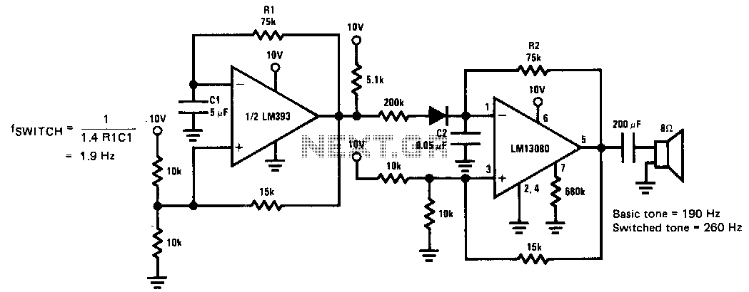
This siren provides a constant audio output while alternating between two distinct tones. The LM13080 is configured to oscillate at a fundamental frequency. This frequency can be modified by connecting a 200 kΩ charging resistor in parallel with the...
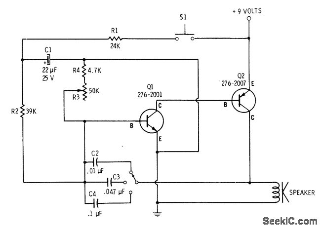
The tone is adjustable through a multiposition switch that changes capacitors in the oscillator circuit. The speed, or rate of frequency change, of the siren is controlled with resistor R3. A 4700-ohm resistor is placed in series with R3...
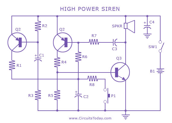
A siren circuit diagram that generates a strong, high-power siren or alarm sound using complementary transistor pairs BC 557 and BC 337, arranged as an oscillator. The described siren circuit employs a pair of complementary transistors, BC 557 (a PNP...