
GSM Remote Control 2 IN and 2 OUT DTMF

The modular remote control system is designed to enhance user interaction with various electronic devices through a flexible and customizable interface. This system typically consists of a microcontroller unit (MCU), wireless communication modules, and an array of input/output (I/O) components. The modular design allows for easy integration of additional features such as sensors, actuators, and user interface elements.
The microcontroller serves as the central processing unit, executing firmware that interprets user commands and manages communication with connected devices. Wireless modules, such as Bluetooth or Wi-Fi, facilitate remote operation, enabling users to control devices from a distance. Input components may include buttons, touchscreens, or rotary encoders, while output components can consist of LEDs, displays, or motors.
The application developed from this modular remote control can be tailored to specific user requirements, allowing for the addition of unique functionalities. For instance, it may incorporate smart home automation features, enabling users to control lighting, heating, and security systems seamlessly from a single interface.
Overall, the modular remote control system exemplifies versatility in electronic design, allowing for continuous enhancements and adaptations to meet evolving technological demands. This project not only demonstrates the potential for innovative applications but also serves as a foundation for future developments in remote control technology.h5. Introduction In this post we present the last application created from the development of the modular remote control we started describing in the issue of April.. 🔗 External reference
Related Circuits
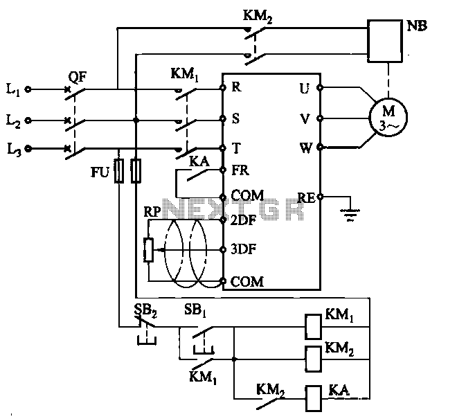
Electromagnetic brake motors consist of a motor and an electromagnetic brake, forming a standard assembly. The circuit diagram is provided. In this configuration, FR represents the forward run and stop command terminal, while the intermediate relay KA is employed...
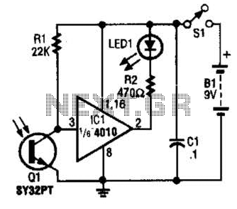
The IR Tester circuit indicates whether the button pressed on a remote control is functioning. Q1 is a phototransistor that is activated by infrared (IR) energy. The IR Tester circuit operates by detecting infrared signals emitted by remote control devices...
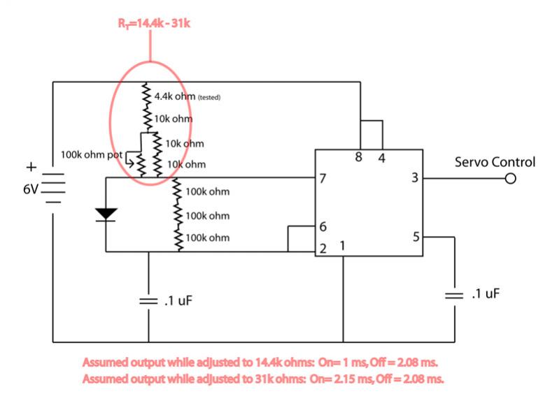
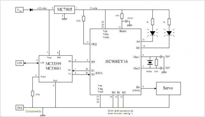
The circuit is not providing the full range of motion for a servo, only achieving approximately 90 degrees. Assistance is requested to review the circuit. To address the issue of limited servo motion, it is essential to analyze the circuit...
This is a remote on-off switch circuit. This circuit allows the use of a small switch to control larger AC currents from high-power devices. The remote on-off switch circuit operates by utilizing a low-power control signal to manage a high-power...
Design your own Printed Circuit Boards Sprint-Layout is a simple but powerful tool to create layouts for single-sided and double-sided PCBs (Printed Circuit Boards). More: The software comes along with all functions that are necessary for board design. Even...
System Oscillator Crystal/Ceramic Oscillator. The following circuit combination of resistors, capacitors, and inductors depicts an equivalent circuit for a crystal or ceramic oscillator. The system oscillator, specifically a crystal or ceramic oscillator, utilizes a combination of passive components, including resistors,...