
Dual Litz Honeycomb Coils Crystal Radio
The circuit includes three dual gang variable capacitors, each with a capacitance of 270 pF per section, sourced from the surplus market. The antenna input capacitor consists of one section at 270 pF. However, tuning at the top of the broadcast band can be sensitive. To address this, a second antenna terminal connection places the two sections in series, effectively halving the maximum capacitance. The capacitor adjacent to it operates in parallel with the antenna coil, providing a maximum of 540 pF when both sections are combined. The main detector tuning capacitor has one section directly connected across the tank coil, while the other section includes 270 pF in series with the coil, resulting in a maximum capacitance of 400 pF, allowing for full band tuning. The capacitors feature a 2:1 gear arrangement, enhancing tuning precision. The main detector tuning incorporates a 6:1 vernier drive connected to the 2:1 gear, allowing six full turns to rotate the capacitor 180 degrees.
This project includes two complete crystal sets. The first detector connects to the antenna coil and capacitors, while the second detector links to the detector tank circuit. Audio outputs are routed to a front panel selector switch before reaching the audio output transformer. The detectors employ a modified Hobbydyne detector circuit, with a small trimmer to set the loading on the tank circuits, improving both matching and selectivity. Although not verified, it is believed that signal loss is minimal. In the previous model, #61, the detectors were disconnected from the capacitor to reduce losses when using the alternate detector, but this was found unnecessary due to the light loading on the tank, so this feature was omitted in the #62.
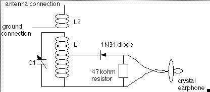
A parallel combination of a 47k ohm resistor and a 0.1 µF capacitor balances the DC resistance with the transformer impedance to prevent tank loading during strong signal reception due to increased diode conductance. This circuit is referred to as the "benny." The radio employs a pair of FO-215 high-performance germanium diodes, although 1N34A diodes are also compatible. A four-point brass link switch is included to select the impedance that best matches the headphones, positioned out of the way since it is typically set only once. For users who frequently change headphones, relocating the switch to the front panel may be advisable, while those who do not can directly wire the preferred tap to the headphone jack.
The base is constructed from an 8x12 inch (20x30 cm) piece of Garolite®, with a thickness of 3/16 inches (approximately 4.5 mm). The front panel measures 4.5 inches (11.5 cm) and has been cut for aesthetic appeal. Although extending the coupling adjustment to the front panel was suggested, the absence of plans or drawings made this impractical. The final design is substantial and stable on a table, with commendable reception quality, particularly during winter months when signals are more plentiful. Selectivity remains satisfactory given the components used. Labels were created using a Brother P-Touch label maker connected to a computer, ensuring clarity without excessive labeling.I hope that this crystal set is well received by all of you. My #62 radio combines the features of some of my earlier radios. It combines the one piece approach of my #48 set and the dual detector of one of my recent sets. The coil arrangement is a dual honeycomb coil, both mounted in an clear acrylic tube. So the coupling between the coils can be adjusted, one of them is on a pivot and can be turned with a knob. If better selectivity is desired, the antenna coil can be rotated perpendicular to the main coil. This reduces the coupling between the coils, making a sharper signal peak. The coils are made with 165 strand, 46 gauge litz wire. This circuit will also work with a spider or space wound coils. The litz can have 44 gauge or 46 gauge conductors, depending on your budget. The three variable capacitors are dual gang types with 270 pf capacitance per section. These were obtained on the surplus market. I made them work very well in this radio. For example, the antenna input capacitor is one section at 270 pf. But at the top of the broadcast band, the adjustment can be a little touchy. By adding the second antenna terminal connection, which places the two sections in series, the maximum capacitance is cut in half. The capacitor next to it is used in parallel with the antenna coil. Both sections are tied in parallel for a maximum of 540 pf. The main detector tuning capacitor has one section directly connected across the tank coil, while the other section has 270 pf in series going to the coil.
This gives a maximum capacitance of 400 pf. I am able to tune the entire band using the full range of the capacitor. The capacitors also have a 2:1 gear arrangement. This makes the tuning a little nicer. The main detector tuning has a 6:1 vernier drive connected to the 2:1 gear, giving 6 full turns to turn the capacitor 180 degrees. What bliss! There are two complete crystal sets in this project. The first detector is connected to the antenna coil and capacitors. The second detector is connected to the detector tank circuit. The audio outputs are wired to a front panel selector switch and routed to the audio output transformer.
The detectors use a modifiedHobbydynedetector circuit. A small trimmer sets the loading on the tank circuits. This improves the match and the selectivity. I haven`t actually checked it, but I believe that the loss of signal is minimal. In my #61 set, I did disconnect the detectors from the capacitor because I thought this would help reduce the losses when using the other detector. I found this not to be a problem because of the feather touch loading on the tank. So I left that feature out of this radio. There is a parallel combination of a 47k ohm resistor and a. 1uf capacitor. This is used to balance the dc resistance with the transformer impedance. This is done so that when strong signals come in, the tank won`t be loaded due to the heavier conductance of the diode.
This little circuit used for this purpose has been named the benny. I used a pair of FO-215 high performance germanium diodes in this radio. 1N34A diodes will also work. I also added a 4 point brass link switch to select the impedance that closely matches the headphones used. This is in an out of the way place as it usually gets set only once. If you change headphones a lot, you might want to locate the switch on the front panel. If you never change headphones, just pick the right tap and wire it directly to the headphone jack. The base is made from a 8x12 inch (20x30cm) piece of Garolite ®. the thickness is 3/16 inches or about 4, 5 mm. The front panel is 4-1/2 inches or 11, 5 cm. I cut the front panel to give a little extra eye appeal to this radio. It was suggested that I could add length to the coupling adjustment and bring it to the front panel, but since I don`t use plans or drawings when I build, it would have made the project a lot more difficult.
I like how this turned out. This radio is quite heavy and sets well on my table. The reception is very good. I sure like testing these sets during the winter. More signals. The selectivity is good, considering the components. I haven`t mentioned this in a while, I made the labels with a Brother P-Touch label maker that is connected to my computer. I try not to over label. I put enough on so you know what the controls are for. That`s about it. If you have questions, please ask. 🔗 External reference
Related Circuits
The coil on the left is coil #1, and has 17 taps. The other coil is coil #3. The vertical strips are the lath material, screwed to the 1 foot long base. Holes drilled in the ends of the...
The UTC A6966 is designed for driving a 5 LED level meter and comes in a 9-lead SIP package. It includes one input amplifier and five comparators for LED level indication. Manufactured by LianShun Electronics Co., Ltd. The UTC A6966...
The interface uses a PIC16F876 microcontroller and not much else. It performs channel mixing, current limiting, and noise rejection. Push the stick forward, both motors move forward, move the stick to the left and the robot moves left. It...
The intersection of industry and data collection systems includes hydrometeorological control systems, robot control systems, and digital image transmission systems. This is facilitated by the electron transport of data information. The data transmission system is a crucial component of...
The switcher output connects to the single vertical input of the oscilloscope, while a sync line from one of the inputs is routed to the oscilloscope's external-sync input. The frequency response of the input amplifiers reaches 300 kHz across...
The ADC12038 family consists of 12-bit plus sign sampling Analog-to-Digital Converters (ADCs) featuring serial input/output. These devices are equipped with configurable analog multiplexers that can accommodate 2, 4, or 8 input channels. Upon request, these ADCs can execute a...