
EMF Probe Version 2
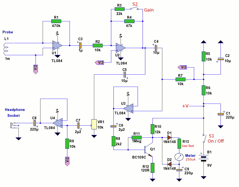
This stage has switchable gain of approximately 1. 5x and 4. 7x controlled by S2. The output gain of both U1 and U2 stages ( with switch S2 open ) is about 70dB at 1KHz. Gain is still about 30dB at 400KHz, although the signal meter will not be too accurate at such high frequency. The bode plot simulated in LTspice is shown below: The output from U2 is split by C4 and C5 and drives an independent headphone amplifier built around U4.
VR1 acts as a volume control the output being either a mono or stereo miniature jack plug as shown. The output stage of the TL084 is sufficiently low to drive 32 ohm headphones like Sennheiser or Ipod Shuffle, etc. U3 forms part of the signal meter circuit. U3 is wired as a voltage follower, the EMF signal has any DC component removed by C6 and then passed to the meter driver circuit based on Q1 and associated components.
Q1 is a BC109C transistor, although a 2N2222 transistor could be used as an alternative part. Q1 is a common emitter amplifier with a voltage gain of about 10, set by the ratio R10 / R12. R8 acts to increase input impedance to the stage and also helps to linearise the gain. The voltage at Q1 collector is high enough to bias diodes D1 and D1 which act as a full wave rectifier circuit across the meter. C9 has a large value, this is so the meter can respond to low mains frequencies of 50Hz. The signal meter used has a full scale deflection FSD of 250uA. If a similar rated meter is used R13 is not needed. If greater sensitivity is required then a 100uA or 50uA meter may be used. In this case the meter circuit may become too sensitive so R13 can be introduced, its value should be about 4x the meters coil resistance, or can be left out altogether for a very sensitive meter circuit.
The Maplin meter is shown below. This signal meter is available from Maplin Electronics part number LB80B and has a FSD of 250uA and an internal resistance of 675 ohms. However any meter will work having a similar sensitivity. Meters of 100 or 50uA FSD can also be used providing a suitable series resistor is used. Because the circuit is responding to RF frequencies up to several hundred kHz a smoothing capacitor across the meter should not be used as this would appear as an effective short circuit reducing the average current through the meter to zero.
The probe is made from an old pen tube, the end cap being removed. A 50cm length of audio screened cable is threaded through the pen tube and soldered to the radial inductor. The capacitance of 50cm audio cable is about 2pF, longer cable should not be used as high frequency performance will deteriorate.
The cable may be used with a 3. 5mm mono plug and socket if desired. My completed probe is shown below. The diameter of the inductor fitted neatly against the body of the pen tube. A layer of insulating tape or glue may be used to secure the pen body to the inductor. To model this circuit in LTspice or any other simulator you have to take into account the input capacitance of the probe cable, and the impedance of the inductor itself. The cable capacitance was measured by a capacitance meter and came out at 1. 9pF, so 2pF was added in parallel with L2 which is the probe inductor. The simulation schematic is shown below: The Toko 8RB inductor has a series resistance of 7 ohms, at 100kHz the impedance is 628.
3 ohms. The series resistance of L2 needs to be included, in LTspice the inductor L2 can be right clicked and a value for series resistance entered, or as shown above can be entered in the value of Rs. A transient response at 10kHz is shown below: The simulation model has 3 nodes labeled Vgain, Vheadphone and Vmeter for clarity.
These waveforms are shown above. The input has been simulated by a signal generator feeding another coil. The coupling coefficient of 0. 9 is used and input voltage of 10mV pk-pk used. The simulation circuit for LTspice can be downloaded here. Unzip the file and then load the circuit. The file now contains models for the potentiometer and TL072, which is the same model as the quad TL084 model. If you have access to an audio or RF signal generator you can apply an input signal to the windings of a small transformer or another inductor.
This will set up an electromagnetic field which will be easily detected by the probe. Without a signal generator, just place the probe near a power supply, mains wiring or other electrical device. There will be a deflection on the meter and sound in the headphones if the frequency is below 15KHz. Over 15kHz, sounds will be inaudible, but there may be harmonics, but the meter circuit will still respond up to 400kHz.
I made a simplified test circuit on breadboard. U1 and U2, were replaced by a single stage, with 2. 2Meg resistor for gain. The final stage was the voltage follower and FW meter circuit as shown below. Meter leads disconnected for clarity Red and Black circle mark connection points. The mains wiring with no load gave a defelection of 0. 5 (25uA) on the 250uA meter. The signal from wiring on a 60 Watt desklamp was stronger with a reading of about 2 and the electro magnetic field from a transformer gave full scale deflection from several inches away. Switch on, set VR1 to minimum and plug in headphones (optional). The circuit can be built on veroboard and is designed to be portable. Try moving the probe near a light switch or electric socket and a loud hum will be heard in the headphones and meter will deflect.
We aim to transmit more information by carrying articles. Please send us an E-mail to wanghuali@hqew. net within 15 days if we are involved in the problems of article content, copyright or other problems. We will delete it soon. 🔗 External reference
Related Circuits
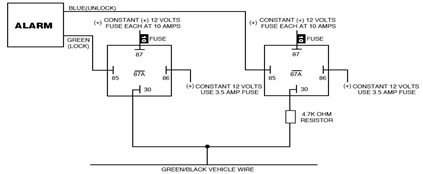
The following circuit illustrates the Ford Probe Single Wire Door Alarm System. This Single Door Locking Wire manages both LOCK and UNLOCK functions, indicating that the pulse wires must be connected to the same vehicle wire. The system primarily...
Logic testers are simple yet very useful devices for testing digital circuits. A logic probe can be designed in various ways. Logic testers, commonly referred to as logic probes, are essential tools in the field of digital electronics. These...
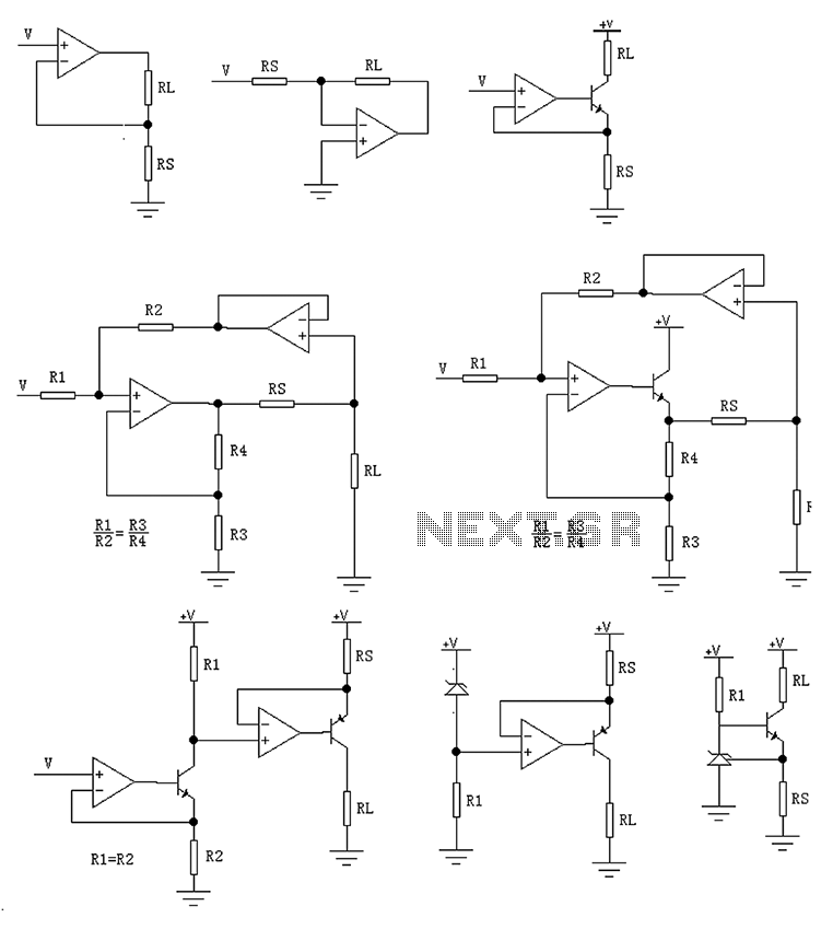
The circuit is designed to provide several constant current outputs to the load resistor RL. The first RL is floating and is rarely utilized. The second RL serves as a virtual ground and is not commonly used either. The...
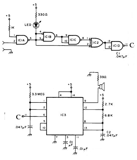
The NE556 timer can function as an indicator for the static state of a digital logic audible terminal. An audible logic probe is beneficial for visually inspecting a component while simultaneously checking the logic state at another point far...
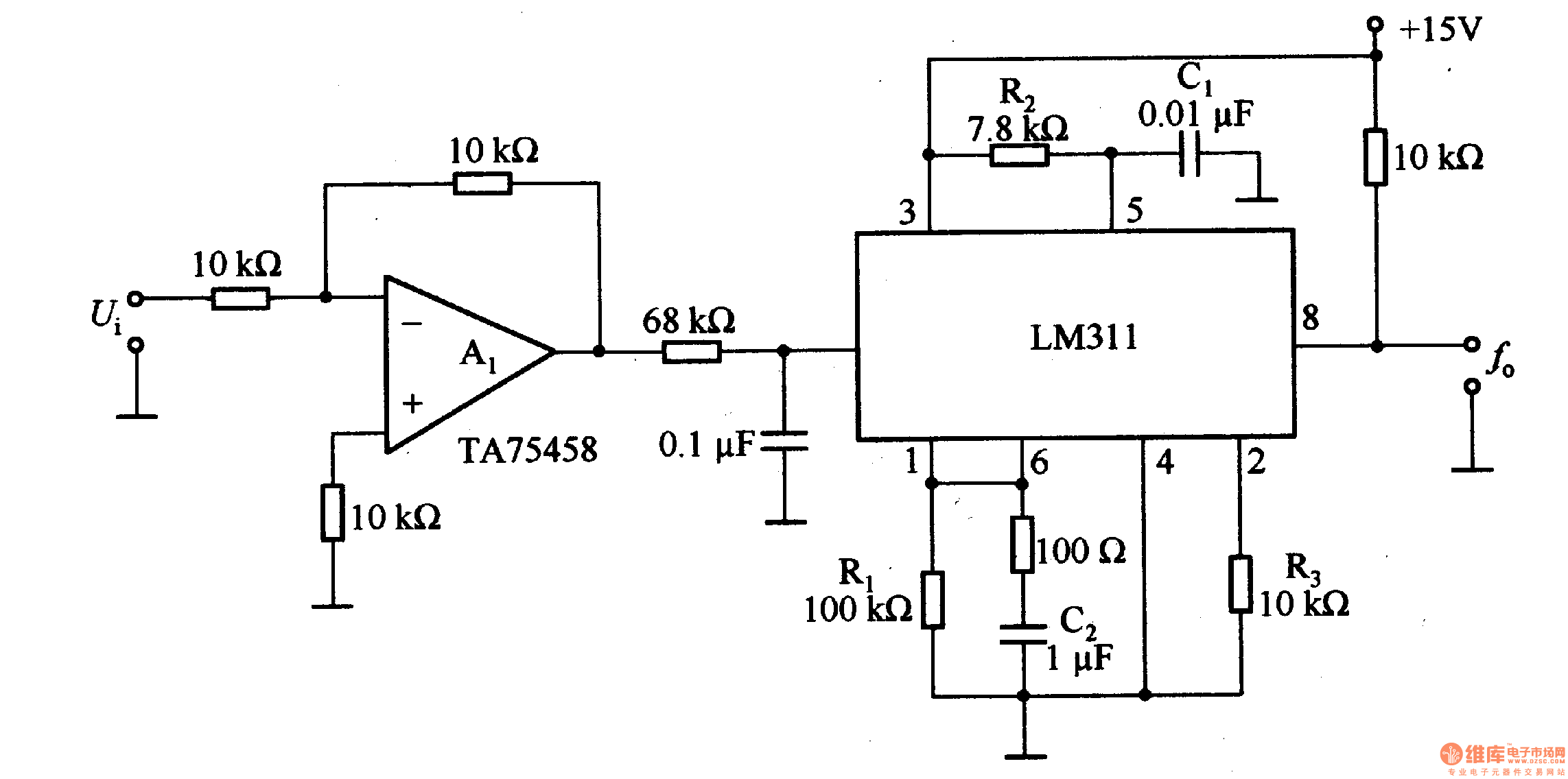
The LM311 is an integrated circuit that functions as a reference voltage generator, comparator, amplifier, and discharge circuit. It is designed for ease of use. In the circuit, the output frequency f0 is... The LM311 is a versatile integrated circuit...
Many of the date circuits may be familiar as they resemble those used in other projects. The VFO and RF input bandpass filters are each designed around bowl resonators, which can be challenging to source. A HPF505 type diode...