
How To Use A Cmos 4017 As A Toggle Switch
This circuit is based on the CMOS 4017 decade counter, which is commonly used in various counting applications due to its straightforward operation and reliable performance. The 4017 features ten output pins, each corresponding to a decimal count from zero to nine. In this specific application, only the first three outputs (pins 2, 3, and 4) are utilized, allowing for a simple two-state toggle operation.
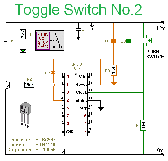
The operation begins with the 4017 counter initialized at a count of zero, indicated by a high signal at pin 3. The clock signal applied to pin 14 increments the counter. Each press of the button effectively acts as a clock pulse, causing the output to transition from low to high at pin 2, activating the relay and illuminating the LED. The use of R2 to limit the base current protects the transistor from excessive current, ensuring longevity and reliability.
The toggle function is achieved through the interaction of the counter outputs and the reset mechanism. When the button is pressed to advance the count to two, the output at pin 2 goes low, which deactivates the transistor and consequently de-energizes the relay. The subsequent high state at pin 4 triggers a reset through D2, returning the counter to its initial state.
The capacitor C2 plays a crucial role during power-up, ensuring that pin 15 is momentarily driven high before returning to low, thus resetting the counter to zero. R3 acts as a discharge path for C2, allowing for a swift reset and ensuring the counter is ready for operation.
Overall, this circuit exemplifies a practical application of the CMOS 4017 decade counter in a toggle switch configuration, providing a reliable method for alternating the state of a relay based on a simple push-button interface. The design takes into consideration the necessary components to ensure proper operation while maintaining simplicity and functionality.This circuit uses a Cmos 4017. The 4017 is a decade counter. The count starts at zero. And it advances by one - each time pin 14 is taken high. When the count reaches nine - it goes back to zero - and starts all over again. = As the count progresses - each of the output pins goes high in turn. The first is pin 3 - it represents zero. The second is pin 2 - it represents one. Pin 4 represents two - and so on. The number represented by each output pin is shown in red. = Although the 4017 will count up to nine - we are only using it to count up to two. Consequently - most of the output pins are unused. Unused Cmos output pins should always be left unconnected. = The circuit uses two output pins and two input pins. The outputs are - one and two - at pins 2 & 4 And the inputs are - Clock & Reset - at pins 14 & 15. = The output at pin 2 is used to control the relay. When the count reaches one - pin 2 will go high. When pin 2 is high - it`s connected internally to the positive line. And it supplies base current to the transistor - through R2. = The resistor limits the base current to under 5mA. This is more than enough to switch the transistor on. When the transistor switches on - it connects the negative side of the relay coil to ground. And this causes the relay to energize. = The transistor does a second job. It connects the negative side of the LED to ground. The LED is acting as an indicator. If the LED is lighting - you know that the relay is energized. The 4mA or so - provided by R1 - should make it bright enough for this purpose. = When the button is pushed - and the count moves on to two - pin 2 will go low again. When pin 2 is low - it`s connected internally to the negative line. As a result - it can no longer supply base current to the transistor. So the transistor switchs off - the relay de-energizes - and the LED is extinguished. = This is a toggle switch circuit - so we want the push button to energize and de-energize the relay alternately. That is - we want the push button to change the state of pin 2. = Consider what happens when we turn on the power. The count begins at zero. In other words - pin 3 will be high. And the rest of the output pins will be low. Of course - pin 3 is not part of the circuit. So nothing else will happen. = When you push the button - the count will advance to one. In other words - pin 2 will go high - and pin 3 will go low. When pin 2 goes high it energizes the relay - in the manner described above. And the LED lights. = The next time you push the button - the count will advance to two. In other words - pin 2 will go low - and pin 4 will go high. When pin 2 goes low - the relay de-energizes - and the LED switchs off. = When pin 4 goes high - it takes pin 15 high - through D2. This resets the counter to zero. Causing pin 4 to go low - and the zero output to go high again. = Now we`re back where we started. Pin 3 is high - pin 2 is low - the relay is de-energized - and the LED is off. The next time the button is pressed - the count will advance to 1. Pin 2 will go high - the relay will energize - and the LED will light. = We`re in a sort of loop. We start off at zero - with the relay de-energized. The first push of the button advances the count to one - and energizes the relay. The next push attempts to advance the count to two. But this resets the counter to zero - and we`re back to the start again. = THE ROLE OF C2 & R3 = To be certain that the count will start at zero - C2 & R3 perform a reset when power is first applied.
To reset the counter to zero - pin 15 must first be taken high - and then taken low again. The first task - that of taking pin 15 high - is performed by C2. And the subsequent task - that of taking pin 15 low again - is performed by R3. = At power-up - C2 is in a discharged state. In this condition - it acts like a wire link joining pin 15 to the positive line. In other words - C2 takes pin 15 high. = R3 charges 🔗 External reference
Related Circuits
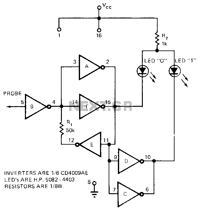
The circuit requires only the CD4009AE hex buffer, two resistors, and two LEDs to create a logic probe. This CMOS logic probe has an input impedance of 10^12 ohms and operates within a voltage range of 3 to 15...
The headlights of a 2001 Chevy S10 sometimes function and sometimes do not, along with the dashboard indicator light. All other lights are operational. The headlight switch, fuse, and relay have been replaced, and the headlight bulbs have been...
This is a simple circuit that does the day/night switchings you have in mind. POT1 is used to set the light level at which the circuit switches from enable to disable. The described circuit functions as an automatic day/night switch,...
Touch operated switches are an attractive project for DIY electronics but they are not so common in commercial products. The reason for this is that, although there are many different ways of implementing a touch switch (leakage, hum pickup,...
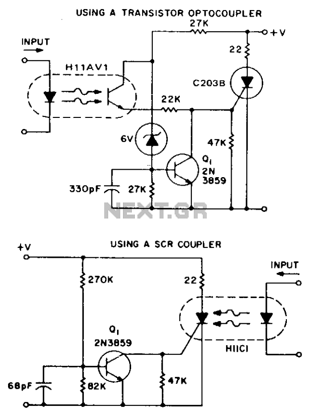
These two simple circuits provide zero voltage switching. They can be used with full wave bridges or in antiparallel to provide full wave control and are normally used to trigger power thyristors. If an input signal is present during...
A relay (RL1) is activated with a 100-second delay when a +12V power supply is connected to the circuit. Figure 2 illustrates a relay timer circuit utilizing a 555 timer, featuring two time ranges: 6-60 seconds and 1-10 minutes...