
Infrared Model Train Detector Circuit
This infrared model train detector circuit provides a practical solution for enhancing model railway systems by enabling automatic detection of trains. The integration of the LM567 PLL Tone Decoder allows for reliable signal processing, ensuring that the system can accurately identify the presence of trains based on the reflected infrared light. The use of the CNY18-2 opto-coupler ensures electrical isolation between the detector circuit and any connected external systems, which can include alarms, automated signals, or other control mechanisms.
To optimize the performance of the circuit, careful attention should be paid to the positioning of the infrared components. D1 should be aligned to emit infrared light directly onto the track, while D2 must be positioned to receive only the light that is reflected back by the train wagons. This setup minimizes false triggering from ambient light sources and enhances the reliability of the detection system.
The choice of infrared emitters and detectors is crucial; they should be selected based on their wavelength compatibility to ensure efficient operation. Additionally, the tuning of resistor R2 is essential, as it influences the sensitivity of the detector. Depending on the reflective properties of the model train wagons, adjustments to R2 may be required to achieve the desired detection range and response time.
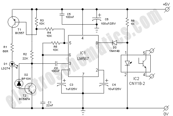
Overall, this circuit design is an excellent addition to any model railway enthusiast's toolkit, allowing for enhanced automation and control over train operations through efficient detection mechanisms.This simple and economical IR model train detector circuit is intended especially for those hobbyists who wish to add a smart sensor to detect trains on their model railway track. As can be seen in the schematic diagram, it comprises of a simple infrared transmitter and receiver wired around the good old PLL Tone Decoder LM567(IC1).
It has a worki ng range of around 10 to 50 cm. Output of the detector is galvanically isolated with the help of a standard opto-coupler CNY18-2 (IC2), which can be suitably interfaced to any external circuit for further processing task(s). Working of the circuit is straight forward. When light from Infrared sender (D1) is relected by the wagon of the model train, IC1 through Infrared photo sensor (D2) receives the recovered signal at its input point (pin3).
If PLL (IC1) is locked, its output (at pin8) drops low, thus disabling the optocoupler IC2 for the specific time and this process repeats based on the number of wagons. Infrared componets D1 and D2 should be mounted such that D2 can only pick up reflected light. When a train passes, the infrared light is reflected at certain intervals, which produces a sort of pulse code` for the train.
Using an external circuit connected through IC2, it is possible to distinguish various model trains from each other using the pulse code! The choice of D1 and D2 is not very critical, but they must be band compatible. Operating point of the detector is dependent on refleted light levels and value of the resistor R2 (here 22K) may need to be tuned` for optimum performance.
🔗 External reference
Related Circuits
NiCd battery charger schematic and description. This NiCd battery charger circuit can charge 12V, 6V, and 9V battery packs. The NiCd battery charger circuit is designed to efficiently charge nickel-cadmium (NiCd) batteries, specifically those with voltage ratings of 12V, 6V,...
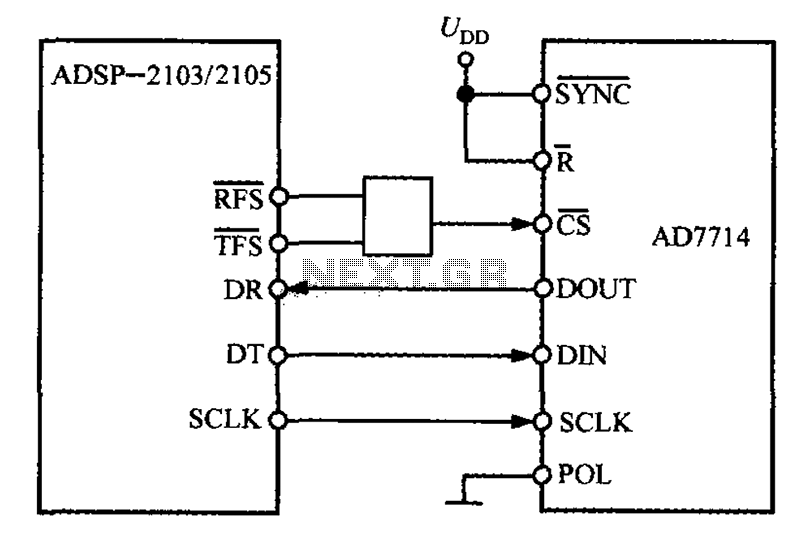
The ADSP-2103 and ADSP-2105 are digital signal processors that interface with the AD7714. When the output is active, the ADSP-2103/2105 configuration includes the RFS non-TES non-terminal set to a low level, while the SCLK terminal is configured for serial...
This is a simple 1.5V powered LED flasher circuit diagram. This circuit can flash 1.7V or 2.3V LEDs (depending on the color) using a 1.5V DC input. The LED will turn on when the 100µF capacitor is charged by...
A simple CATV upstream fiber optic receiver utilizes DC pilot automatic gain control (AGC). Upstream fiber links in a community antenna television (CATV) system are often challenging to align correctly. Set-top boxes and cable modems use "long-loop" AGC. Additionally,...

This design circuit is a tachometer circuit based on the LM2907 integrated circuit, which can provide zero-crossing data to a digital system. At each zero crossing of the input signal, the charge pump alters the state of capacitor C1...
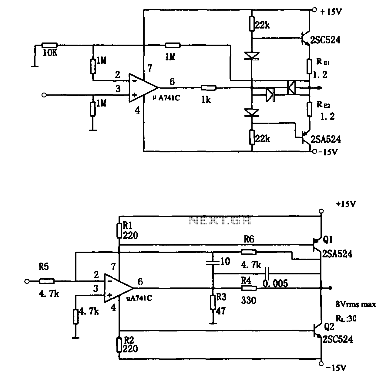
The direct coupling audio power amplifier utilizes an integrated operational amplifier. There are typically two practical configurations. The first configuration, depicted in (a), features a circuit structure that includes the output of the operational amplifier and a complementary symmetry...