
Infrared Remote Control
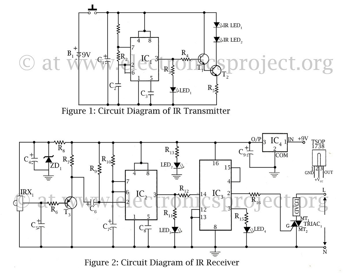
The infrared remote-controlled switch operates using a 555 timer integrated circuit (IC), which is configured in a monostable mode. This allows the circuit to be triggered by an infrared (IR) signal emitted from a compatible remote control. The primary function of the switch is to control an electrical load, such as a lamp or a fan, remotely.
The circuit consists of several key components: the 555 timer IC, an IR receiver module, a transistor, a relay, and associated passive components like resistors and capacitors. The IR receiver module detects the IR signals from the remote control and converts them into an electrical signal. This signal is fed into the trigger pin of the 555 timer.
When the 555 timer is triggered, it generates a high output signal for a predetermined duration, which can be set by adjusting the resistor and capacitor values connected to the timer. The output from the 555 timer is used to drive a transistor, which in turn activates a relay. The relay acts as a switch, controlling the power to the connected load.
The design allows for flexibility in controlling different types of loads, as long as they fall within the relay's specifications. The circuit is suitable for various applications, such as home automation systems, where convenience and remote operation are desired.
In summary, this infrared remote-controlled switch project highlights the integration of a 555 timer IC with an IR receiver to create a simple yet effective remote control mechanism for managing electrical devices.infrared remote controlled switch is second remote controlled project in this website using 555 ic circuit diagram with description of remote controlled switch. 🔗 External reference
Related Circuits
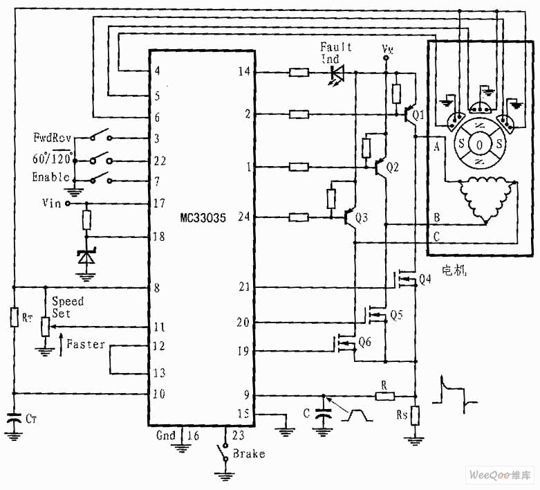
The presented three-phase application circuit features a motor controller circuit connection diagram that operates using a full-wave six-step method. The power switch is a Darlington PNP type, while the lower power switch is an N-channel power MOSFET. Each device...
Most cases of infrared remote control failure can be identified by the absence of the pulsed transmitted infrared light. It is very rare that the... Infrared remote controls operate by transmitting modulated infrared light signals that are detected by a...
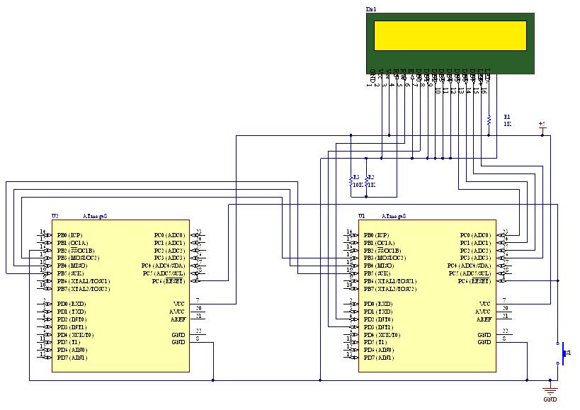
SPI stands for Serial Peripheral Interface, which is the simplest among all communication protocols. Eight-bit data registers in the devices are connected by wires. These data registers function as shift registers, with one device controlling the data exchange within...
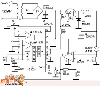
The PWM control dimming circuit for a halogen lamp is illustrated. The halogen lamp operates at a rated voltage of 12V with a nominal power of 20W. This dimmer circuit is capable of adjusting the intensity of the halogen...

This device features a small DC motor fan situated above a container filled with deodorant liquid or gel, powered by a D cell battery. A photocell is integrated to deactivate the fan in low light conditions. An LED indicator...

The Wildcard requires a minimum of 8 volts on the V+Raw power rail, which must not exceed 26 volts. When using the Docking Panel or Power Dock, the V+Raw rail is automatically connected. If not using a dock, manual...