
High Resolution 24-bit Data Acquisition System instrument-control

The 24/7 Data Acquisition Wildcard is designed for high-performance data acquisition applications, featuring a robust architecture that accommodates various sensor inputs. The use of a 24-bit sigma-delta ADC enables high-resolution measurements, making it suitable for applications that require precise data collection. The continuous sampling capability allows for real-time monitoring of analog signals, which is essential in many industrial and research settings.
The configuration options for the input channels provide flexibility in how data is collected. Users can choose between differential and pseudo-differential configurations, allowing for adaptation to different types of sensor outputs. This versatility is particularly beneficial in environments where multiple sensor types are deployed, as it allows for optimal signal integrity and measurement accuracy.
The integration of programmable gain amplifiers and digital low-pass filters further enhances the system's performance. These components allow users to tailor the signal conditioning process to the specific requirements of their application, ensuring that noise is minimized and the desired signal is accurately captured.
In terms of connectivity, the Wildcard's design emphasizes ease of integration with existing systems. The absence of keyed connectors, while requiring careful handling during installation, enables a more compact and versatile design. This feature is particularly advantageous in applications where space is limited or where multiple modules need to be interconnected.
Overall, the 24/7 Data Acquisition Wildcard represents a sophisticated solution for data acquisition tasks, combining high-resolution measurement capabilities with flexible configuration options and robust software support. Its design considerations ensure that it can be effectively utilized in a wide range of applications, from industrial monitoring to academic research.This Wildcard requires 8 Volts or greater to be present on the V+Raw power rail. The V+Raw rail should not be greater than 26 Volts. If you are using the Docking Panel or Power Dock, the V+Raw rail is connected for you. If you are not using a dock, you will need to connect V+Raw yourself. For the QCard : see QCard Appendix B. For the PDQ Board: s ee Appendix B Power Header. High-level software routines allow you to initialize, calibrate, configure, and control the 24/7 Data Acquisition Wildcard. Once commanded to start converting, the analog to digital converter continually samples and converts at a fixed rate.
You can read the output once, or store each sequential conversion to a memory buffer. You must sample one channel at a time; changing channels requires restarting the conversion process with a different channel specified. Fig. 1 Block diagram of the high resolution data acquisition system, showing its 24-bit sigma delta analog to digital converter with digital low pass filter and programmable gain amplifier.
Analog inputs and reference voltages for sensor excitation are accessed on its field header. The above figure diagrams the WildCard. Signals are taken from the Field Bus on the left. The eight inputs may be configured in four pairs, for four differential input channels, or they may be configured as seven pseudo-differential inputs with the eighth line acting as a common return. Power and reference voltages are provided to the field header for your use. You can configure the converter to use the 2. 5 volt internal reference, or to take its reference from the field header. Many sensors and measurement methods produce an output that is ratiometric; that is, an output proportional to a reference signal or that is accompanied by its own full scale reference signal.
You can accurately measure these by providing an appropriate reference voltage to the reference inputs on the field header. The last sections of this document provide an example code listing, a glossary, and the complete schematics of the 24/7 Data Acquisition Wildcard.
If after reading this document you have further questions, please consult this data sheet for the AD7714, which is also provided with the distribution diskette and located at. Please take time to read through the example programs that illustrate how to effectively use the pre-coded software drivers.
There are many subtleties involved with using the 24/7 Data Acquisition Wildcard that are highlighted in the example code. Fig. 2 Functional block diagram of the AD7714 24-bit analog to digital converter. The input channels are further protected and multiplexed on the Data Acquisition Wildcard. (from the AD7714 datasheet) The Wildcard bus does not have keyed connectors. Be sure to insert the module so that all pins are connected. The Wildcard bus and the Analog I/O Wildcard can be permanently damaged if the connection is done incorrectly.
If you are using a Wildcard Carrier Board and QED Board, connect the Wildcard Carrier Board to the QED Board as outlined in the "Wildcard Carrier Board Users Guide". If you are using another controller the WildCard plugs directly into the controller. With the power off, connect the 24/7 Data Acquisition Wildcard to the Wildcard Carrier Board or to your Controller by connecting the Wildcard Bus of the 24/7 Data Acquisition Wildcard (labeled Wildcard Bus) to Module Port 0 of the Wildcard Carrier Board (located below the QED Digital I/O header and to the right of Module Port 1) or of your controller.
Caution: The 24/7 Data Acquisition Wildcard or your controller can be permanently damaged if the connection is done incorrectly. Be sure the jumper shunt for J1 is not installed on the 24/7 Data Acquisition Wildcard. With the jumper shunt not installed, the reference voltage for the analog to digital converter is set to 2.
5 volts. Be sure the jumper shunts for J2 and J3 are not installed on the 24/7 Data Acqu 🔗 External reference
Related Circuits
A cathode follower based on the 6BL7 or 6BX7 is ideal for output. I used a mu-follower circuit with no feedback, a 12SN7 as the gain stage, and a 6BL7 as the cathode follower/current source. You might argue that...
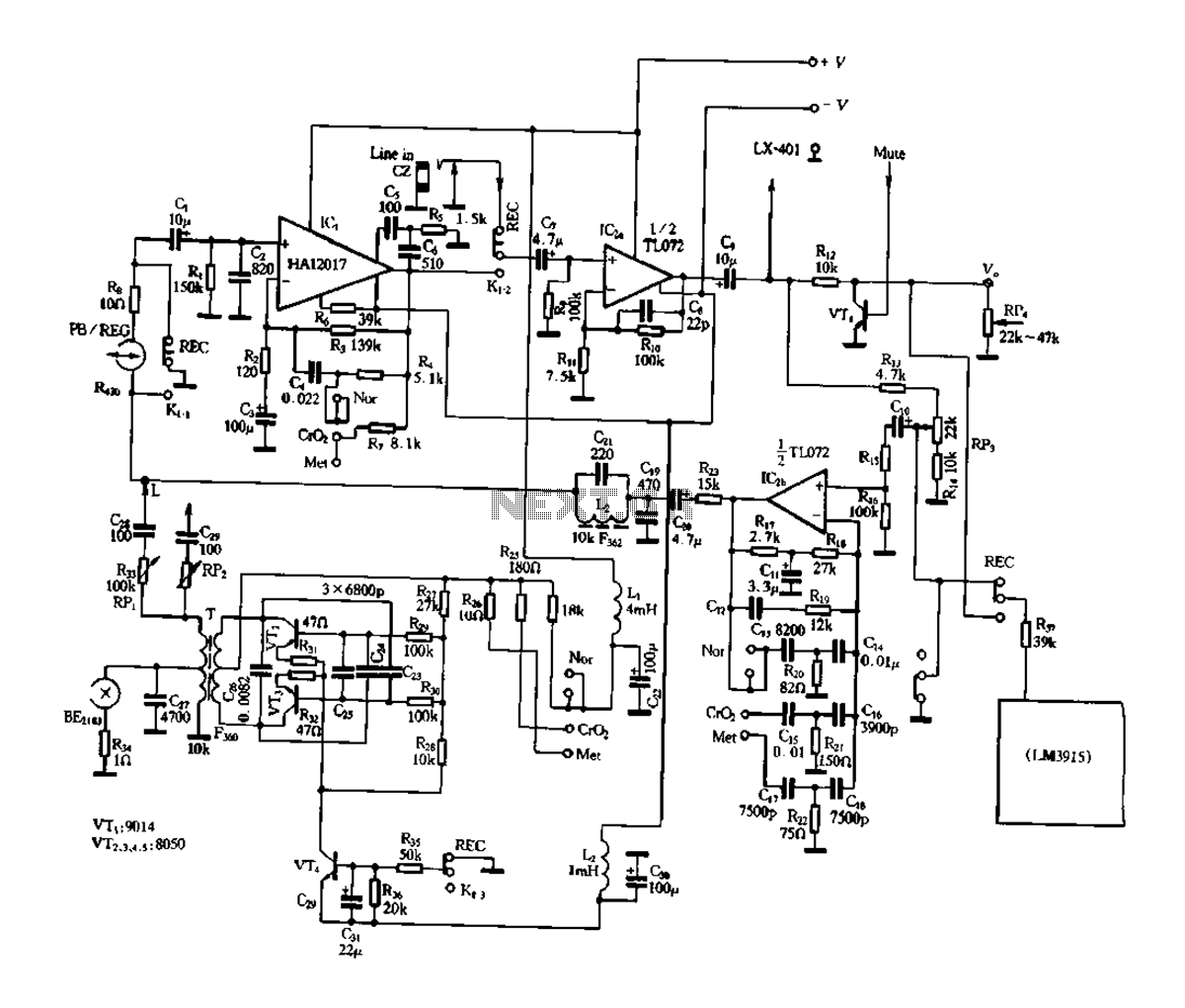
Figure 3-17 illustrates a pre-equalizer amplifier with sound recording capabilities, featuring the following characteristics: (1) The circuit does not utilize a conventional mechanical switch circuit; instead, it employs fully enclosed electromagnetic relays. This design allows for a core and...
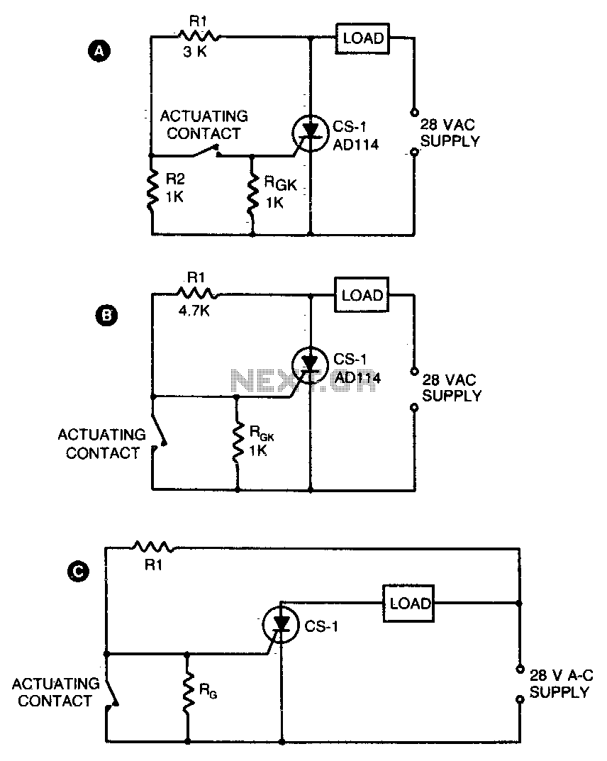
Two simple arrangements for resistive loads are shown in A and B. The circuit in A will provide load power when the actuating contact is closed, and no power when the contact is open. B provides the reverse of...
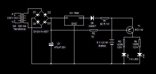
This is a high-efficiency emergency lamp that utilizes high-brightness white LEDs. It automatically activates during power failures and deactivates when power is restored. The emergency lamp circuit is designed to provide reliable illumination during power outages, utilizing high-brightness white LEDs...
This circuit is designed to demonstrate high-frequency high voltage, capable of producing voltages up to approximately 30 kV, depending on the transformer used. It is economical and straightforward to construct, primarily utilizing a standard TV flyback transformer. The circuit...
The mine railway connects the national railways and intermediate links of the mining area, serving as an important component of the railway transport network. Statistics indicate that the Chinese mine railway extends over 20,000 kilometers, with numerous road junctions...
Warning: include(partials/cookie-banner.php): Failed to open stream: Permission denied in /var/www/html/nextgr/view-circuit.php on line 713
Warning: include(): Failed opening 'partials/cookie-banner.php' for inclusion (include_path='.:/usr/share/php') in /var/www/html/nextgr/view-circuit.php on line 713