
Interfacing LM35 Temperature Sensor with PIC Microcontroller
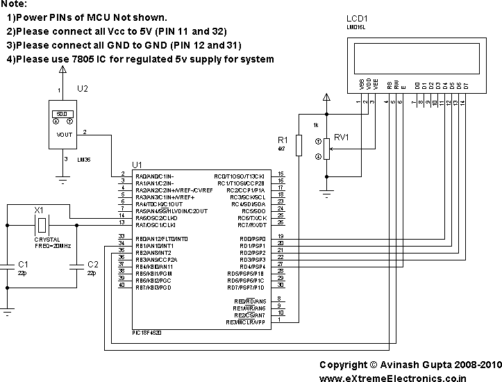
The LM35 temperature sensor is a precision integrated-circuit temperature sensor that provides an output voltage linearly proportional to the Celsius temperature. It operates within a temperature range of -55°C to +150°C and has an output scale factor of 10 mV/°C. This means that at 0°C, the output voltage will be 0V, and at 25°C, it will generate an output of 250 mV.
To interface the LM35 with a PIC microcontroller, the following steps are typically involved:
1. **Circuit Design**: The LM35 sensor is connected to an analog input pin of the PIC microcontroller. It requires a power supply, usually +5V, which can be provided by the microcontroller. A bypass capacitor may be added to the power supply line to filter out noise.
2. **Analog-to-Digital Conversion (ADC)**: The PIC microcontroller will convert the analog voltage output from the LM35 into a digital value using its built-in ADC. The ADC resolution will determine the precision of the temperature readings. For example, an 8-bit ADC will provide values ranging from 0 to 255, while a 10-bit ADC will provide values from 0 to 1023.
3. **Temperature Calculation**: Once the ADC conversion is complete, the digital value must be translated back into a temperature reading. This can be accomplished using the formula:
\[
\text{Temperature (°C)} = \frac{\text{ADC Value} \times 5V}{1023} \times 100
\]
This equation assumes a 10-bit ADC with a reference voltage of 5V.
4. **Displaying Results**: The results can be displayed on a 16x2 LCD module. The PIC microcontroller will send the calculated temperature value to the LCD for visualization. This typically involves initializing the LCD, setting the cursor position, and sending the temperature data formatted as a string.
5. **Programming**: The microcontroller can be programmed using languages such as C or assembly. The code will include initialization routines for the ADC and LCD, a loop for continuous temperature reading, and the conversion and display logic.
This basic setup provides a foundation for various applications, including environmental monitoring, HVAC systems, and educational projects, showcasing the versatility and importance of temperature sensors in electronics.In present day, variety good sensors are available to measure almost anything. In this tutorial will explore the wonderful world of sensors, starting with a very simple analog temperature sensor LM35. We will learn how to interface it with PIC MCU and display the result in common 16x2 lcd module.. 🔗 External reference
Related Circuits

A simple electric guitar SPICE subcircuit has been designed, which features a signal generator producing a 440 Hz sine wave output at 100 mV. This electric guitar SPICE subcircuit serves as a fundamental tool for simulating the behavior of an...

A sensor activates transistor Q1 to turn on the low-frequency 555 oscillator, which generates pulses to control LAMP II. The sensor may respond to variations in light or temperature. Either resistor RA or RB can function as the sensor,...
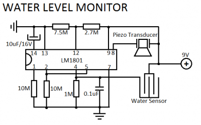
LM1801 Water Level Sensor Circuit Diagram. Features: reference voltage is overshot, and the IC drives the ceramic transducer to beep, low power consumption. The LM1801 water level sensor circuit utilizes the LM1801 integrated circuit, which is designed to monitor water...
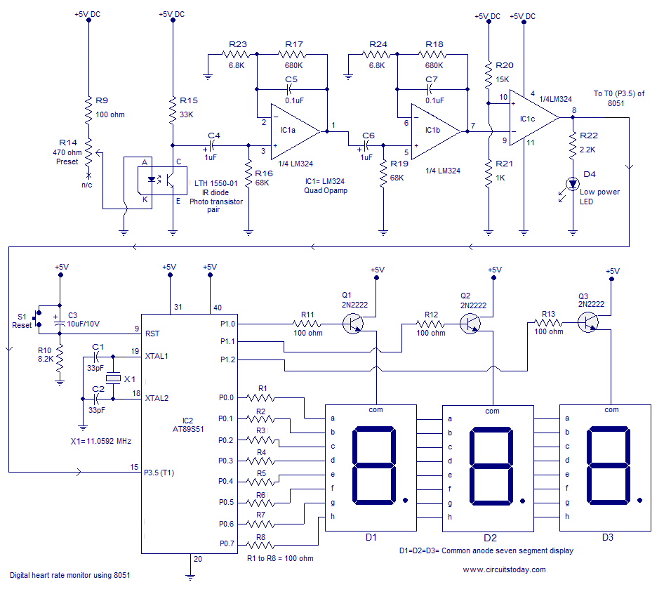
Heart rate monitor using an 8051 microcontroller. It measures the heart rate from the fingertip using an IR diode and phototransistor pair (Photoplethysmography). The AT89S51 microcontroller is utilized in this application. The heart rate monitor circuit operates based on the...
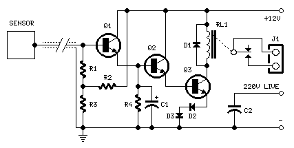
Q1, Q2, and Q3 form a high-impedance super-Darlington configuration that drives the relay, amplifying the 50 or 60 Hz alternating mains supply frequency induced in the sensor by the human body. Capacitors C1, D2, and D3 ensure clean switching...
The initial PIC program utilizing the C language demonstrates how to blink a single LED using a PIC microcontroller with a C program. This serves as an introduction to C programming for PIC microcontrollers. The circuit for blinking an LED...