
Sensor-Activated Relay Pulser Circuit

The circuit utilizes a low-frequency NE555 timer configured in astable mode to generate a square wave output that drives LAMP II. The sensor's operation is critical, as it determines the conditions under which the NE555 timer activates. The choice of RA or RB as the sensing element allows for flexibility; either can be a thermistor for temperature sensitivity or a photoresistor for light sensitivity.
In this configuration, RA and RB should not exceed 100 kΩ to ensure proper functioning of the oscillator. The values of these resistors will influence the timing characteristics of the NE555, specifically the frequency and duty cycle of the output signal. The pulse width and frequency can be adjusted by varying the resistance values and the capacitance connected to the timing pins of the NE555.
When the sensor detects a decrease in resistance (for instance, a rise in temperature) at RB or an increase in resistance at RA (like a decrease in ambient light), the NE555 timer is triggered to output a pulse. This output pulse activates Q1, allowing current to flow through LAMP II, thereby illuminating it. The design can be further refined by incorporating additional components such as diodes for flyback protection, capacitors for noise filtering, and potentiometers for fine-tuning the sensitivity of the sensor.
Overall, this circuit provides a simple yet effective means of controlling a lamp based on environmental changes, showcasing the versatility of the NE555 timer in various applications. A sensor turns on Ql to activate the low-frequency 555 oscillator, which pulses LAMP II. Sensor may be sensitive to changes in light or temperature. Either RA or RB can be sensors, as desired. A decrease in RB or an increase in RA will cause the NE555 to flash M. fl and RB should be 100 kohm max.
Related Circuits
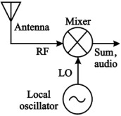
An Autodyne circuit integrates three functions typically found in separate stages of an RF Receiver into a single circuit. These three stages are the RF amplifier, the Mixer, and the Local Oscillator, which are usually interconnected. In a standard...
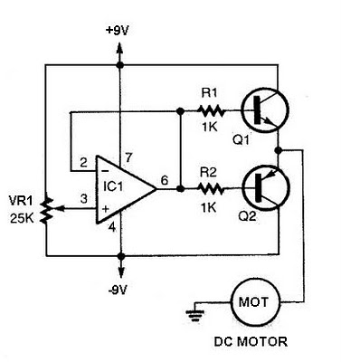
The speed increases in either direction as the potentiometer VR1 is adjusted toward its ends. The TIP3055 Q1 NPN power transistor has a collector current specification of 15A and a VCE0 rating of 60V DC. The MJE34 Q2 PNP...
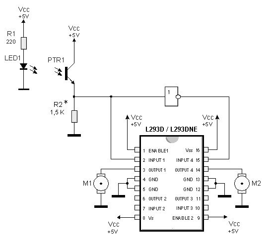
By utilizing logic chips, the behavior of a robot can be enhanced, allowing for the implementation of more complex algorithms. Logic chips, also known as logic gates or digital logic integrated circuits, are fundamental components in digital electronics that perform...
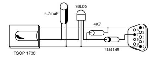
It is unusual that personal computers are not equipped with a standard remote control interface. Many motherboards feature an IRDA port; however, this port is not compatible with the 38 kHz frequencies commonly used by regular remote controls. Fortunately,...
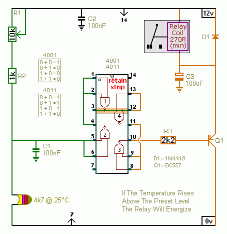
The first circuit energizes the relay when the temperature rises above the preset level. The second circuit energizes the relay when the temperature falls below the preset level. The two circuits are practically identical. The only difference between them...
This circuit is utilized in RS-232 serial interface and current loop circuit applications. It converts voltage signals into a 20mA current signal, with a maximum transmission rate of 1200 bits per second. The CCD IC1 and transistor T1 form...