
Capacitive Sensor

The circuit utilizes a super-Darlington transistor configuration formed by Q1, Q2, and Q3, which is designed to achieve high input impedance and significant current gain. This configuration is particularly effective for detecting low-level signals, such as those induced by the human body through capacitive coupling. The alternating current (AC) frequency of 50 or 60 Hz from the mains supply is amplified, allowing the relay to switch on in response to human presence.
Capacitor C1 serves as a coupling capacitor, blocking any direct current (DC) components and allowing only the AC signal to pass through to the base of the Darlington pair. Diodes D2 and D3 are used for flyback protection, ensuring that any back EMF generated by the relay coil during switching does not damage the transistor components. This arrangement results in a reliable and efficient relay operation.
The power supply requirement specifies the use of a commercial wall plug-in transformer adapter. This adapter should have an integrated rectifier and smoothing capacitor to convert the AC voltage to a stable DC voltage suitable for the relay operation. It is vital that the power supply can deliver adequate current to meet the relay's specifications.
For safety and proper circuit functionality, it is crucial that the circuit ground is connected through a small value, high voltage-rated capacitor to one side of the mains supply socket. This connection helps to isolate the circuit from the mains while allowing it to sense the AC signal. The "Live" side of the mains supply socket must be identified and connected correctly to ensure the circuit operates safely and effectively.Q1, Q2 & Q3 form a high impedance super-Darlington that drives the relay, amplifying the 50 or 60Hz alternate mains-supply frequency induced in the sensor by the human body. C1, D2 & D3 ensure a clean switching of the relay. Power supply can be any commercial wall plug-in transformer adapter with rectifier and smoothing capacitor, capable of suppl
ying the voltage and current necessary to power the relay you intend to use. * For proper operation, circuit ground must be connected via a small value, high voltage-rating capacitor to one side of the mains supply socket. The "Live" side is the right one. 🔗 External reference
Related Circuits
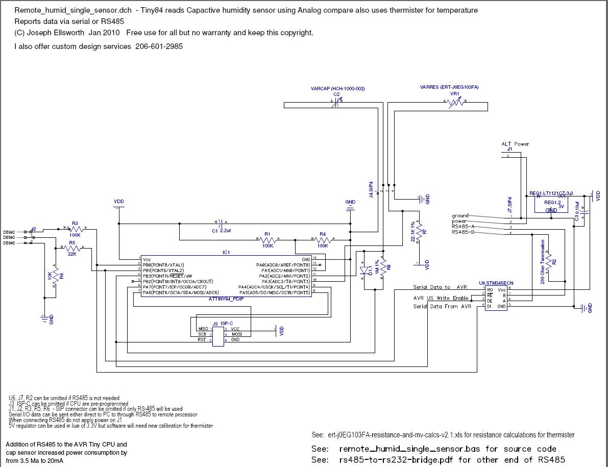
This document explains how to read a capacitive humidity sensor directly from a microcontroller using one resistor, one diode, the sensor, and two I/O lines. This method does not use an ADC but measures the time required to charge...
For proper operation, the circuit ground must be connected via a small-value, high-voltage-rated capacitor to one side of the mains supply socket. The "Live" side is the right one. This circuit is designed to animate shop windows using a...
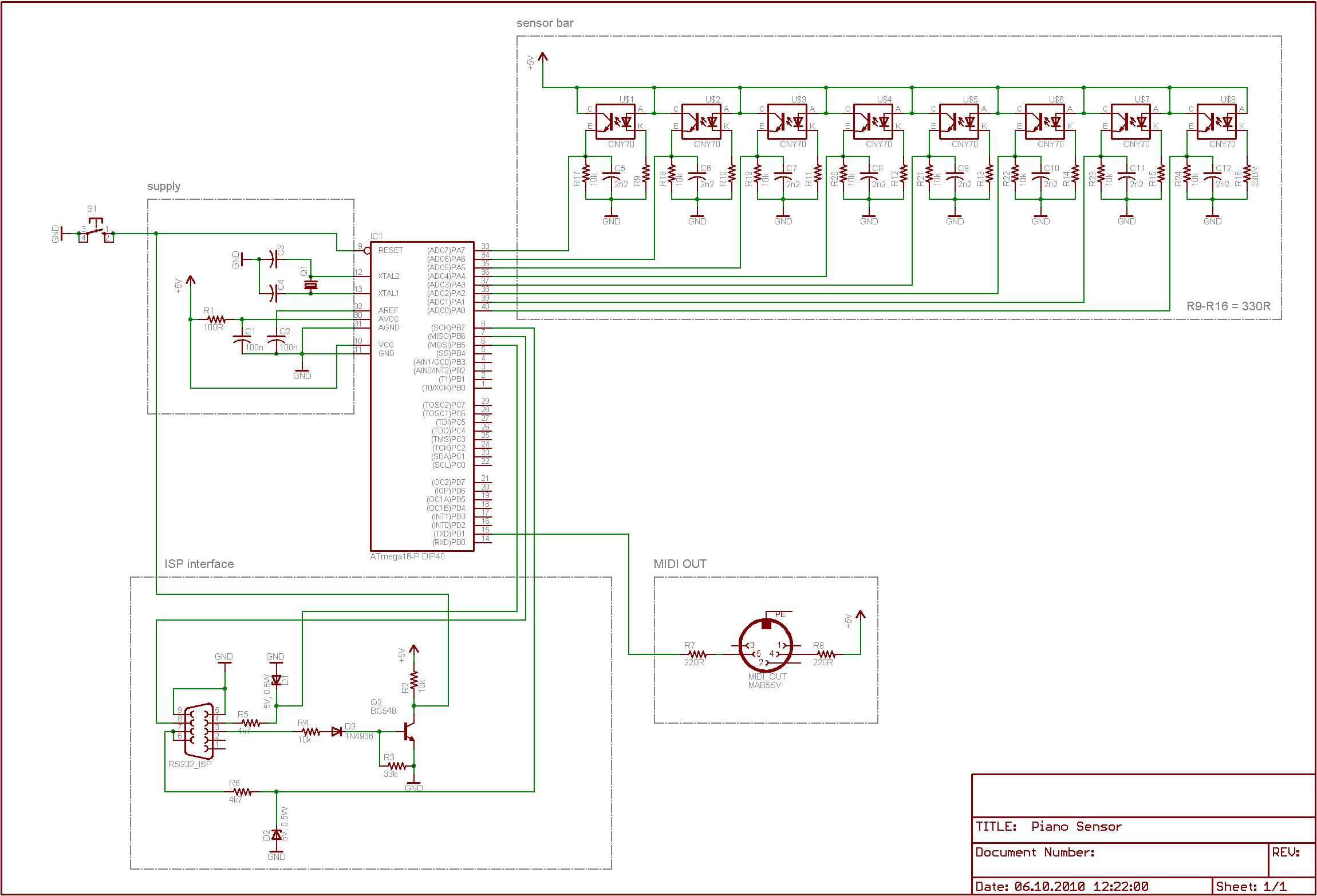
An effort is being made to enhance the responsiveness of an electronic keyboard due to dissatisfaction with the current sensitivity to keystrokes. The initial step in this process involves measuring the speed of the fastest keystroke. To improve the responsiveness...
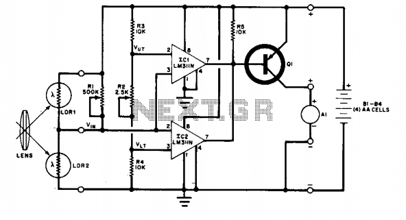
The change in ambient light triggers the alarm by changing the resistance of LDR1 and LDR2. The circuit utilizes two light-dependent resistors (LDR1 and LDR2) to detect variations in ambient light levels. LDRs are passive components that exhibit a change...
The following circuit illustrates the sensor circuit diagram for automatic room lights. This circuit is based on the CD4017 integrated circuit (IC) and features the use of two light-dependent resistors (LDRs). The automatic room light circuit utilizes the CD4017 decade...
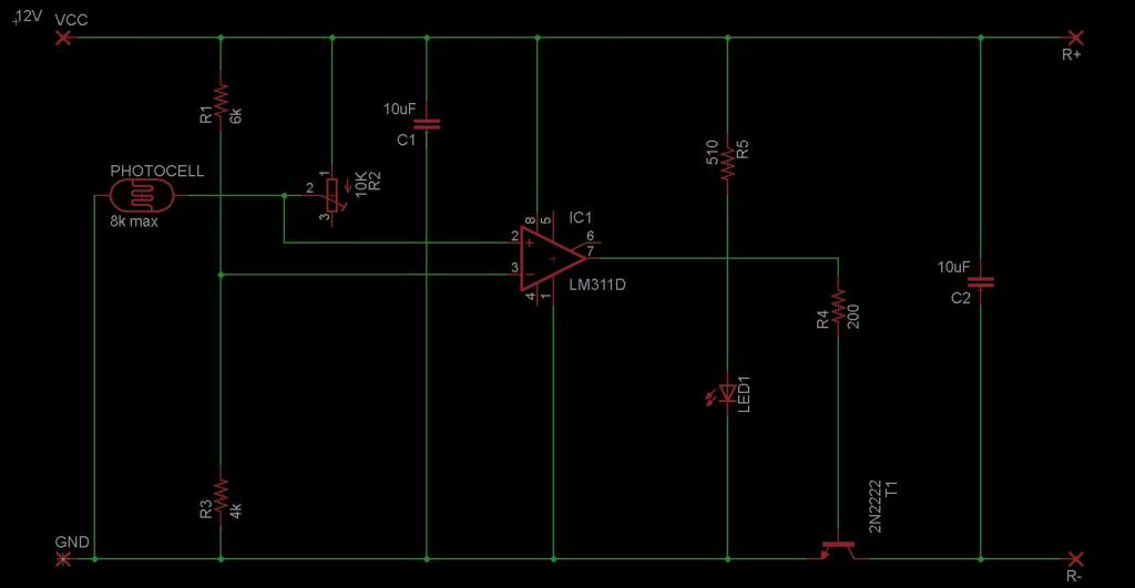
The circuit is designed to sense ambient light levels and activate lights when it is dark. A prototype was successfully built on a breadboard using an LM324 comparator, various resistors, a trimmer resistor, and a photocell. Subsequently, a PCB...