
LED VU Meter by LM339 PCB

The circuit employs LM339 voltage comparators, which are designed to compare two input voltages and output a high or low signal based on the comparison. In this application, the comparators are used to monitor the input signal corresponding to audio power levels. The voltage divider is critical for establishing reference voltages for each comparator, effectively setting thresholds that determine when each LED will light up.
The first comparator is connected to a reference voltage derived from the voltage divider, calibrated to activate the first LED at the desired input level. Subsequent comparators are similarly connected, with their reference voltages set higher, ensuring that each LED lights up at progressively higher input levels. This arrangement allows for a visual representation of audio power levels, providing users with an intuitive way to gauge volume.
The circuit's design can be enhanced with additional features such as an adjustable sensitivity control, which could involve a potentiometer in the input stage. This would allow users to fine-tune the circuit's response to different audio sources or environments.
Power supply considerations for the LM339 include ensuring that the voltage supplied meets the operational requirements of the comparators while providing adequate current to drive the LEDs. Additionally, current-limiting resistors should be included in series with the LEDs to prevent damage from excessive current.
In summary, this circuit serves as a useful tool for monitoring audio power levels through a visual display of LEDs, utilizing the LM339 comparators and a voltage divider to create a responsive and informative volume level indicator.The circuit below uses two quad voltage comparators (LM339) to illuminate a series of 8 LEDs indicating volume level. Each of the 8 comparators is biased at increasing voltages set by the voltage divider so that the lower right LED comes on first when the input is about 400 millivolts or about 22 milliwatts peak in an 8 ohm system.
The divider vol tages are set so that each LED represents about twice the power level as the one before so the scale extends from 22 milliwatts to about 2. 5 watts when all LEDs are lit. The sensitivity can be decreased with the input control to read higher levels. I have not built or tested this circuit, so please let me know if you have problems getting it working.
The power levels should be as follows: 🔗 External reference
Related Circuits
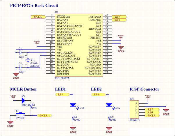
This project involves a basic LED blinking circuit utilizing the PIC16F877A microcontroller. It features two LEDs connected to the PIC16F877A, with the source code adapted from the 16F template. The circuit design consists of the PIC16F877A microcontroller, which serves as...
Many friends have requested an automatic on/off LED circuit or an LED flashing circuit. This post presents an astable multivibrator circuit designed for LED flashing. It is a simple astable multivibrator circuit utilizing two LEDs (specifically red LEDs) and...
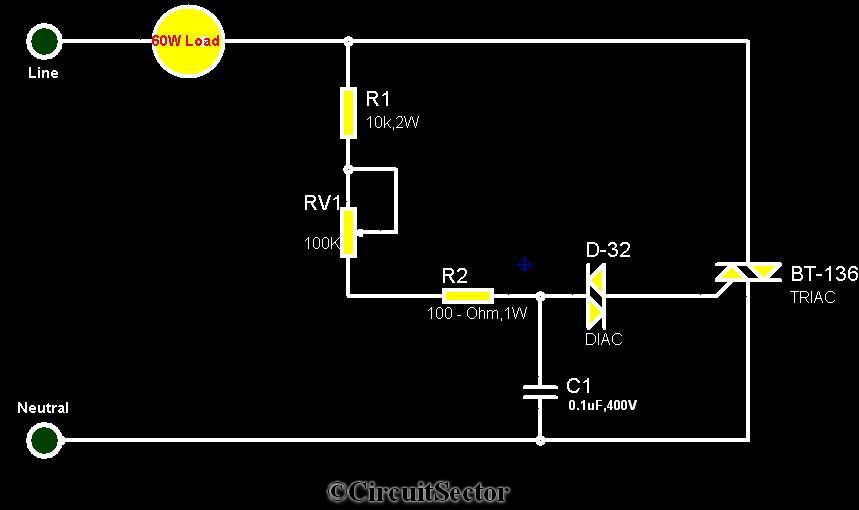
The circuit diagram presented is a triac-diac electronic fan regulator designed to reduce power consumption of electric fans, even at low speeds. Traditional resistor-inductor fan regulators tend to generate excess heat, wasting energy when the fan operates at lower...
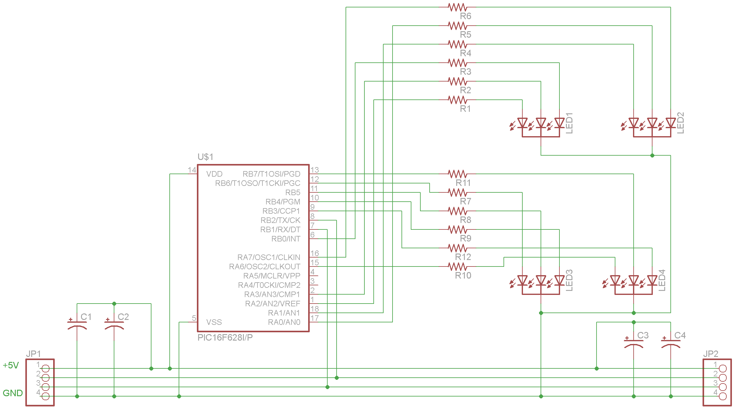
The complete schematic for the driver is provided. A PIC16F628 microcontroller has been selected due to its low cost, internal oscillator (4 MHz), and built-in USART. It is important to note that there is an error in the schematic;...
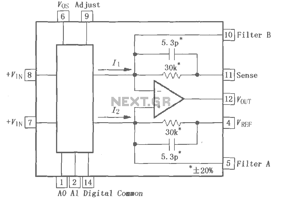
The PGA202 is a digitally controlled programmable gain amplifier with gain settings of G = 1, 10, 100, and 1000. The PGA203 offers gain settings of G = 1, 2, 4, and 8. Both amplifiers are compatible with CMOS...
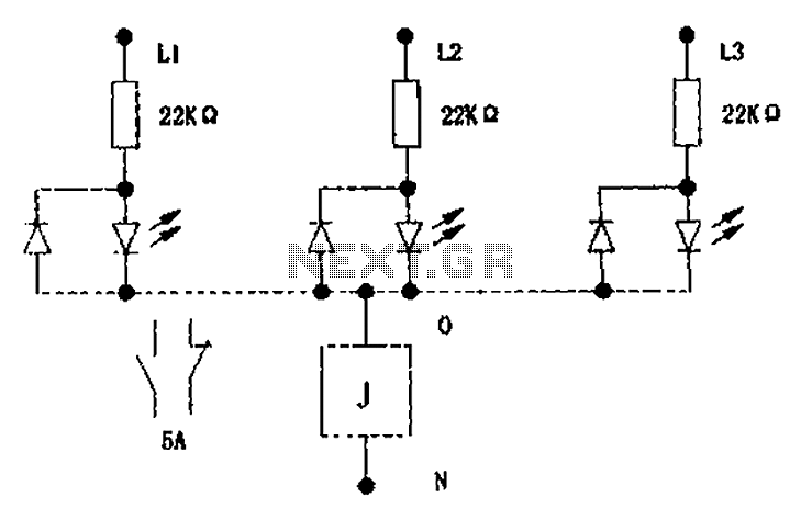
The circuit illustrated below activates a small relay (J) when there is an imbalance in any one phase of a three-phase circuit. This relay triggers an external control contact, which immediately disconnects the power supply to the main circuit...