
Simple Electronic Fan Regulator Circuit PCB

The triac-diac electronic fan regulator circuit is an efficient solution for controlling the speed of electric fans while minimizing energy consumption. The circuit utilizes a triac, a type of semiconductor device that can conduct current in both directions when triggered. The control of the triac is achieved through a diac oscillator, which serves as a triggering device. The D-32 diac is a key component that allows the circuit to switch on at a specific voltage level, providing a sharp transition that enhances the control of the triac.
The resistors R1 and R2 are used to set the biasing conditions for the diac, while the variable resistor RV1 allows for fine-tuning of the oscillator's time period. This adjustment directly affects the firing angle of the triac, which determines how much of the AC waveform is allowed to pass through to the fan motor. By controlling the amount of power delivered to the motor, the fan speed can be effectively regulated without the significant energy losses associated with traditional methods.
The capacitor (0.1uF 400V) in the circuit plays a crucial role in determining the oscillation frequency of the diac. Its value, in conjunction with the resistors, sets the timing characteristics of the oscillator, which in turn influences the firing angle of the triac. The overall design of the circuit emphasizes minimal heat generation and efficient power usage, making it suitable for applications where energy efficiency is a priority.
In summary, the triac-diac electronic fan regulator circuit provides a sophisticated method for adjusting fan speeds, leveraging the properties of triacs and diacs to achieve precise control while maintaining energy efficiency. The ability to adjust the firing angle through the diac oscillator allows for smooth and gradual changes in fan speed, enhancing user comfort and reducing electrical consumption.Circuit The circuit diagram provided is a triac - diac electronic fan regulator that would reduce your power usage of electric fans even in slow speeds. A normal resistor-inductor fan regulator heats up to waste eneegy when the fan is running with lowers speeds or it controls motor speed via applying resistance between fan and power supply.
This l ight dimmer/fan regulator circuit uses the principle of power control using a Tric. The triac turns On and Off varying the firing angle of the Triac. This can be done by a diac oscillator circuit. The diac oscillator consists of D-32 diac, R1, RV1, R2 resistors, a 0. 1uF 400V capacitor. The time period of this diac oscillator can be controlled by adjusting RV1. By doing this we can vary the firing angle of the triac thus the speed of the fan motor. 🔗 External reference
Related Circuits
This is an inexpensive DC voltage doubler circuit diagram that requires a minimal number of components and is capable of delivering 10V from a 5V power supply. If the oscillator needs to be... The circuit operates on the principle of...
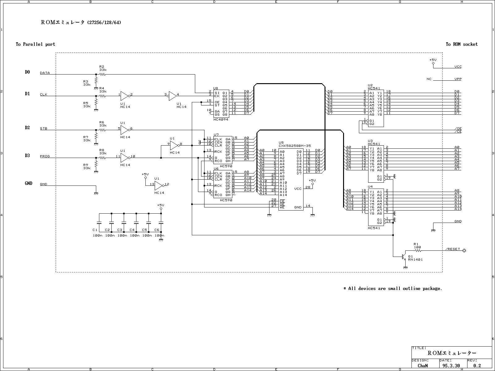
This ROM emulator improves the easiness to build/use it by reducing down its function which can be used as a ROM emulator. The kind of the ROM types to be emulated are 2764, 27128, and 27256. The debugging capability...
Figure 14-41 illustrates a multivibrator circuit utilizing a 555 timer alongside various capacitive and resistive components. The oscillation frequency is determined by the values of Ra, R16, and C3, following the formula f = 1.44 / ((Ra + 2R16)...
A real-time controller is a device designed to continuously manage household devices, both in real-time and according to a predetermined schedule. This article focuses on a series of real-time controllers utilizing the AT89C2051 microcontroller, which serves this purpose effectively....
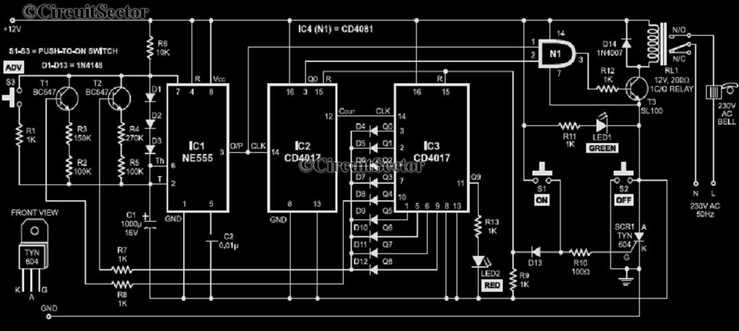
A school operates with a total of eight periods, each lasting 45 minutes, and includes a 30-minute lunch break following the fourth period. A bell is used to signal the start of each class, the end of each period,...
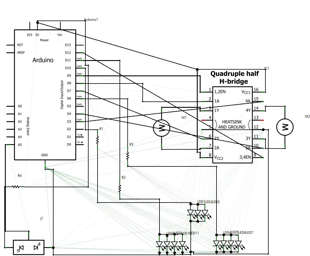
1. Abstract Wet-garden is an interactive flower garden and an ambient indoor sculpture. When people walk around it, it changes motion and LED blinking speed. Wet-design is designed for everyone who wants a tangible interaction object and an interesting...