
Magnetic Field Sensor Circuit
The magnetic field sensor circuit typically employs a Hall effect sensor, which is sensitive to magnetic fields. The Hall effect sensor generates a voltage output that is proportional to the strength of the magnetic field encountered. This voltage can be processed further to indicate the presence and strength of the magnetic field.
The circuit may include a power supply, often a simple battery or DC source, to provide the necessary voltage for the sensor operation. Additionally, a microcontroller or an operational amplifier may be utilized to amplify the signal from the Hall effect sensor, allowing for more precise readings. The output can be connected to an LED for visual indication or to a microcontroller for further digital processing.
To construct the circuit, the Hall effect sensor should be connected to the power supply, ensuring that the polarity is correct. The output pin of the sensor can be connected to an analog input of the microcontroller if digital processing is intended. Alternatively, a simple resistor-capacitor (RC) filter may be added to smooth the output signal, especially if the circuit is intended to detect varying fields.
For audio frequency detection, the circuit may incorporate a bandpass filter to isolate the desired frequency range, allowing the sensor to respond effectively to changes in the magnetic field at audio frequencies. The design can be expanded with additional components such as a display module to visualize the magnetic field strength or a wireless module for remote monitoring.
Overall, this DIY magnetic field sensor circuit is versatile and can be adapted for various applications, including educational projects, hobbyist experiments, or basic magnetic field detection tasks.This DIY magnetic field sensor circuit is very simple and can detect fixed magnetic fields or fields that are varying at an audio frequency. The unit is no.. 🔗 External reference
Related Circuits
This receiver, designed around the popular ZN414 integrated circuit, operates within the AM band frequency range of 550 to 1600 KHz. For Longwave reception, it is necessary to replace the coil, which can be sourced from an old medium...
The following circuit diagram represents a battery charger designed for a 12V car battery. This circuit includes overcharging protection, which automatically disconnects the charging circuit. Unlike typical battery chargers that continuously supply a few amperes to the battery while...
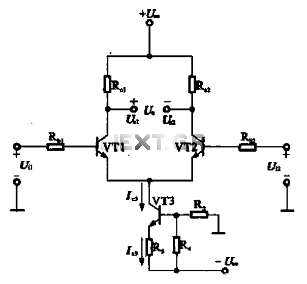
A constant current source is utilized in the differential amplifier circuit, which includes an emitter resistor. In this configuration, an increase in the output voltage (Ua) is not desirable. To ensure that Ua remains stable, the supply voltage (Ucc)...
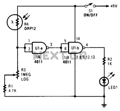
Two gates of a 4011 IC are utilized as a comparator. When the resistance of R4 decreases, the voltage at pins 1 and 2 increases, resulting in a logic zero at pin 3. This causes pin 4 to go...
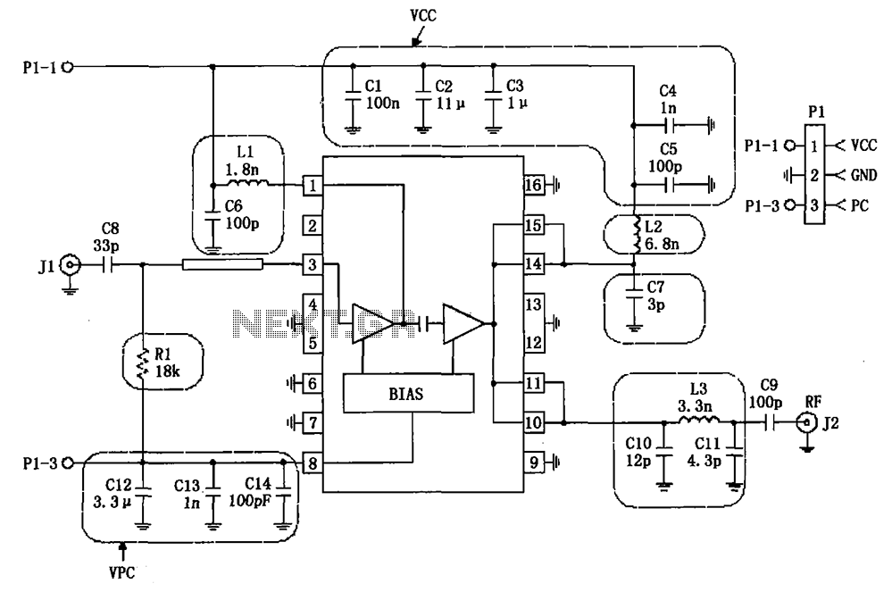
The RF2132 linear power amplifier circuit is depicted in the provided figure. A radio frequency (RF) signal enters through input pin 3 and is processed via a preamplifier. The final stage of the amplifier outputs a gain of 10....
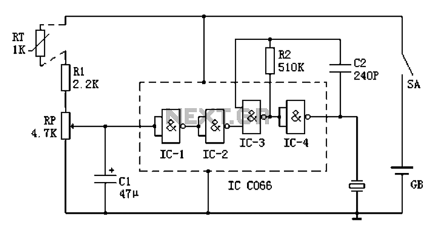
Boiling water on a kitchen gas stove can lead to issues such as spilling boiling water if the process is not monitored, which can extinguish the flame and cause gas leakage. A notification device can address this problem. The...