
ZN414 Portable AM Receiver circuit and description

The circuit design of the receiver emphasizes the use of the ZN414, which is integral to its functionality. The ZN414's architecture allows for effective signal amplification and demodulation of AM signals. The selection of components, including the BC107 transistor and the 1N4148 diodes, is critical for maintaining a stable power supply and ensuring that the receiver operates within its optimal voltage range. The use of a potentiometer for selectivity control allows for fine-tuning of the receiver's sensitivity, which is particularly beneficial in environments with varying signal strengths.
The audio amplification stage, utilizing the 741 op-amp, is designed for inverting configuration, which is common in audio applications for achieving a desired phase shift. The inclusion of the BC109 and BC179 transistors enhances the output current capability, ensuring that the audio signal can drive speakers or headphones effectively. The overall voltage gain of 15 indicates that the output audio signal is significantly amplified compared to the input, making the receiver suitable for practical listening applications.
In summary, this receiver circuit combines a well-regarded integrated circuit with carefully selected passive and active components to deliver a reliable AM radio experience. The design considerations regarding voltage supply, selectivity, and audio amplification contribute to its performance, making it a valuable project for enthusiasts and hobbyists in the field of electronics.Designed around the popular ZN414 ic this receiver covers the AM band from 550 - 1600 KHz with the values shown. For Longwave the coil needs to be changed. Use one from an old MW radio to save time. The ZN414 is a tuned radio frequency designed and incorporates several RF stages and an AM detector. It is easily overloaded and the operating voltage is critical to achieve good results. The BC107 acts as a voltage follower, the four 1N4148 diodes providing a stable 2. 4V supply. With the 10k pot, which acts as a selectivity control, and the b-e voltage drop of the BC107, the operating voltage for the ZN414 is variable from 0 to 1. 8volts DC. If you live in an area that is permeated with strong radio signals, then the voltage will need to be decreased.
I found optimum performance with a supply of around 1. 2 volts. The audio amplifier is built around an inverting 741 op-amp. Extra current boost is provided using the BC109 / BC179 complementary transistor pair. The voltage gain of the complete audio amplifier is around 15. The audio output of the complete receiver is really quite good and free from distortion. I may provide some sound samples later. 🔗 External reference
Related Circuits
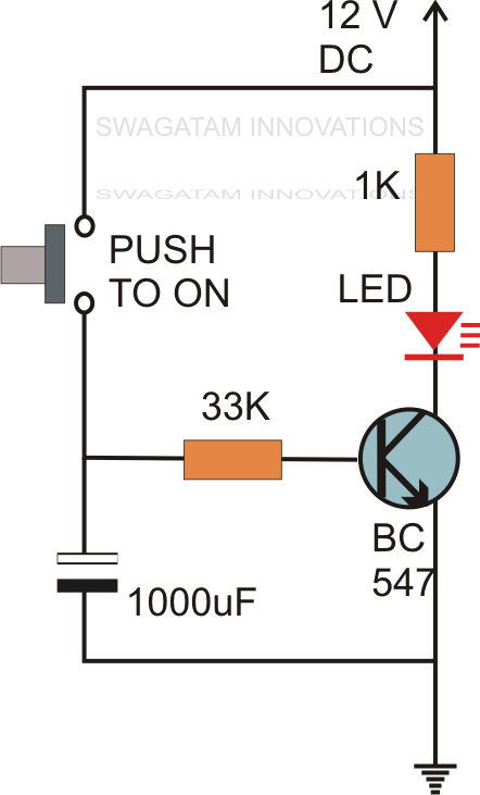
Without the specified delay, the circuit could malfunction or even sustain damage. A capacitor, which is a crucial component of the circuit, is positioned at the other end of the base resistor rather than directly connected to the base...
Each zone uses a normally closed contact. These can be micro switches or standard alarm contacts (usually reed switches). Zone 1 is a timed zone which must be used as the entry and exit point of the building. Zones...
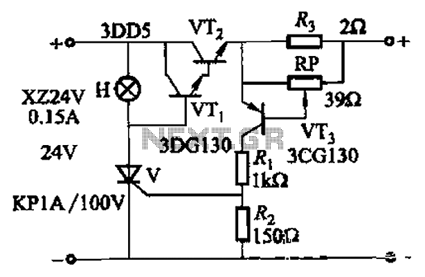
By adjusting Ro or RP, the current setpoint can be modified. The circuit illustrated in Figure 14-98 features overcurrent protection using a thyristor and transistors VTi and VT2, which immediately cut off the power when an overcurrent condition is...
This document outlines modifications made to the RIG RX-2 receiver, enabling remote control via a computer using an RS-232 serial interface. The modifications consist of two components: additional hardware and a new firmware program for the PIC16C84 microcontroller. In...
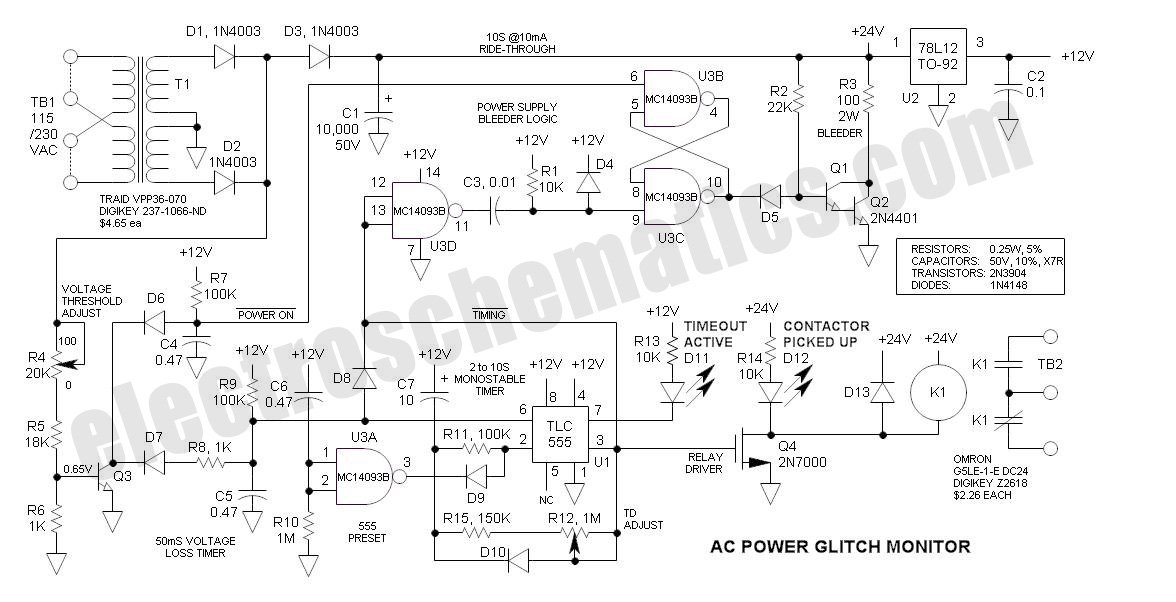
This AC Power Monitor continuously monitors the AC power line voltage for under-voltage conditions and missing cycles. When it detects a total of 5 or 6 consecutive anomalies, it triggers an alert. The AC Power Monitor is designed to provide...
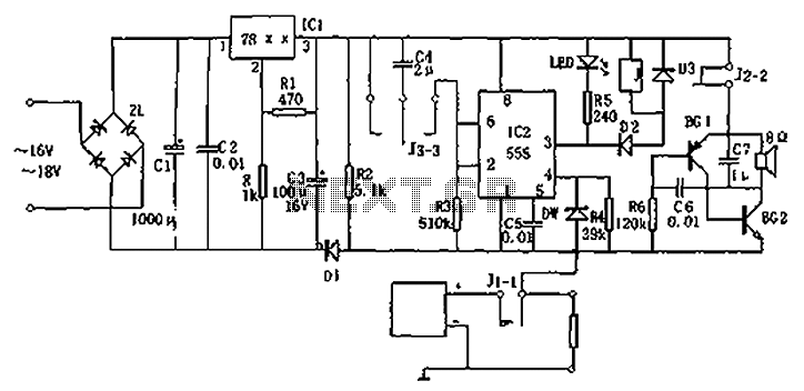
Circuit diagram for a DC power supply protection circuit. The device includes a buck rectifier power supply, a monostable delay circuit, a relay control circuit, and an audio feedback oscillation circuit. The entire circuit operates with a DC voltage...