
Microcontroller In Circuit Serial Programming (ICSP) with Microchip PIC and Atmel AVR
In-Circuit Serial Programming (ICSP) is a technique that allows for the direct programming of a Microchip PIC or Atmel AVR while they remain connected to a circuit, as opposed to programming the chip beforehand and subsequently soldering it into the circuit. ICSP offers numerous advantages, but it also presents critical design considerations that warrant attention.
ICSP facilitates the reprogramming of microcontrollers without the need to desolder them from the circuit, thereby simplifying the development process and enhancing efficiency. This method is particularly beneficial during prototyping and testing phases, where frequent updates to firmware may be required. The ability to program devices in-circuit reduces the risk of damage associated with repeated soldering and desoldering.
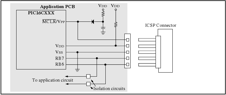
Design considerations for implementing ICSP include ensuring that the programming pins are accessible and that the circuit design does not interfere with the programming signals. It is essential to maintain a clear path for the PGC and PGD signals to avoid signal degradation or noise interference. Additionally, the MCLR/VPP pin must be appropriately managed to prevent unintended resets or erratic behavior during programming.
Careful attention should be given to the layout of the PCB to ensure that the ICSP connections are clearly defined and isolated from other circuit paths. Utilizing dedicated pins for ICSP not only simplifies the design but also enhances reliability during programming sessions. Furthermore, incorporating pull-up resistors on the MCLR/VPP line can help stabilize the programming process and ensure proper operation.
In summary, ICSP is a powerful tool for programming microcontrollers in-circuit, offering significant advantages in terms of efficiency and flexibility. However, careful design and implementation are crucial to maximize its benefits while minimizing potential issues.The programmer uses serial signaling scheme to program the chip in circuit. The signaling is carried through the programming clock (PGC or ICSPCLK) and the programming data (PGD or ICSPDAT) pins. In addition, the MCLR/VPP pin is used as either a high voltage programming signal or an attention indicator to the device.
Wherever application allows, use dedicated pins for ICSP. It will save you much trouble. Not sharing a pin both for ICSP and I/O for example, minimizes the preparation work which needs to be done to allow ICSP. In Circuit Serial Programming is a method of directly programming a Microchip PIC or Atmel AVR while in they are connected to a circuit, as opposed to programming the chip ahead, and only then soldering it to a circuit. There are many benefits to ICSP, but also some important design considerations which I will try to highlight.
🔗 External reference
Related Circuits
The ticking bomb sound generator circuit diagram operates by charging a 2.2 µF capacitor. When the voltage at the base of the NPN transistor reaches 0.65 V, it activates the transistor, which in turn activates the BC557 transistor, increasing...

This circuit is 12 volt motors and lights well regulated. The scheme operates with PWM (Pulse Width Modulation). By IC1, a 555 is a square wave generated by a controllable duty cycle. This means that the width of the...

This circuit quickly charges capacitor CST0 to a voltage that matches an input signal. After charging, the input signal is electrically disconnected from the capacitor, allowing the charge to remain on CST0. Since CST0 is part of the negative...

This circuit features open and closed loop contacts (switches 1, 2, 3) that activate the alarm, which remains on for a duration of 5 to 10 minutes. The triggering delay for entrance and exit is set to 27 seconds....

A DTL integrated circuit comprises a crystal oscillator, which is represented by the integrated circuits. The oscillation frequency ranges from 100 kHz to 1 MHz. Additionally, it includes a gate circuit that supplies a signal for the DTL oscillator...

The circuit illustrated in the figure utilizes the low-drift current source circuit MIC2951, which is designed to provide specific output current values. The MIC2951 is a precision voltage regulator that can also be configured to function as a low-drift current...