
Microcontroller Relay Driver and Interface
Microcontroller systems are versatile platforms that facilitate the integration of multiple interfacing methods to interact with various peripherals and components. These systems often employ digital and analog inputs and outputs to manage tasks ranging from simple control operations to complex data processing.
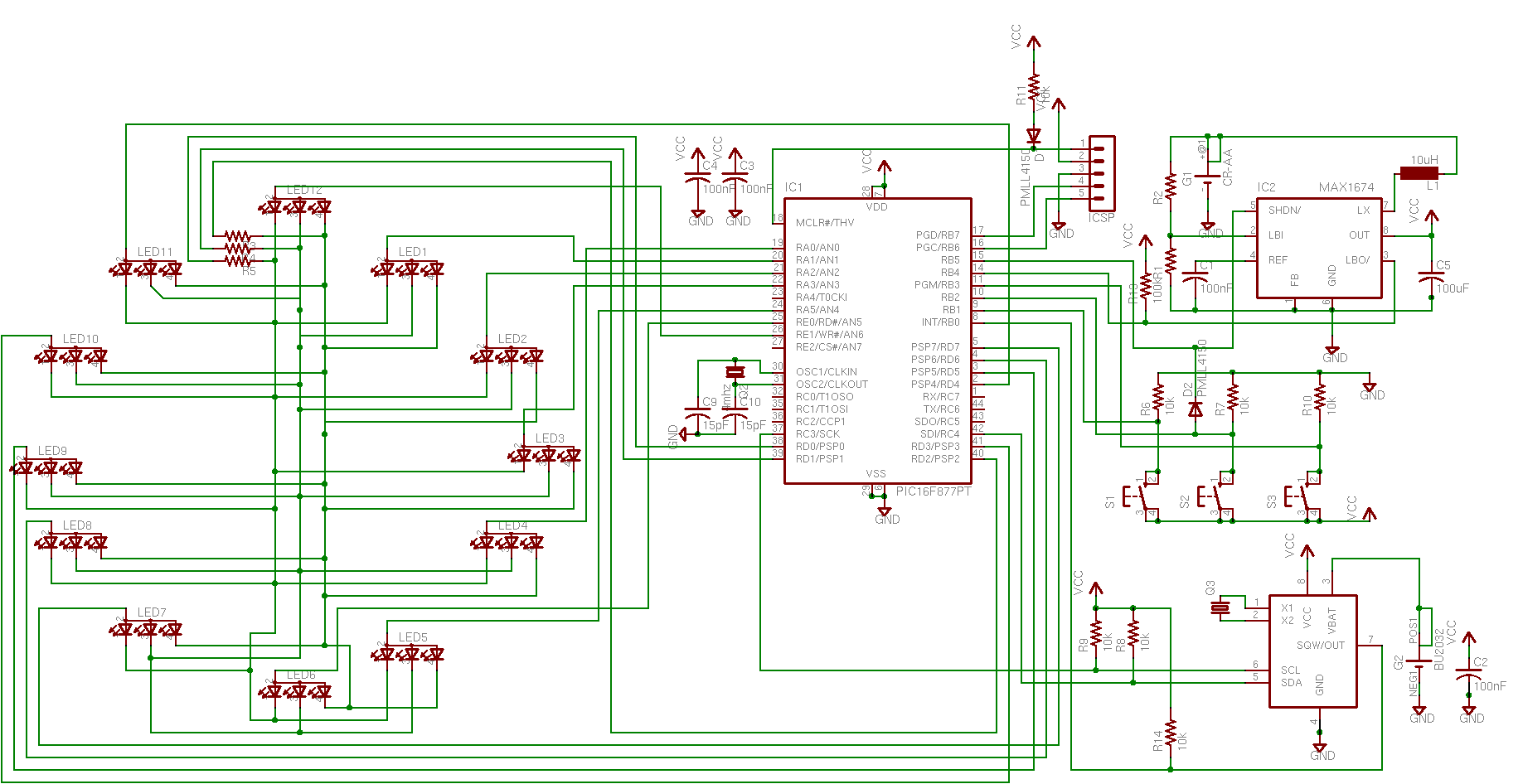
In a typical microcontroller schematic, the microcontroller unit serves as the central processing unit (CPU), which executes programmed instructions and manages the flow of data between different interfacing modules. Common interfacing methods include GPIO (General Purpose Input/Output) pins, ADC (Analog to Digital Converters), PWM (Pulse Width Modulation), and communication protocols such as I2C, SPI, and UART.
The schematic usually features power supply connections that provide the necessary voltage levels to the microcontroller and associated components. It also includes decoupling capacitors placed near the power pins of the microcontroller to stabilize the power supply and filter out noise.
Input devices such as sensors and switches are connected to the microcontroller's input pins. These devices can provide digital signals (on/off states) or analog signals (varying voltage levels), which the microcontroller processes based on its programmed logic.
Output devices, such as LEDs, motors, or displays, are connected to the output pins, allowing the microcontroller to control these components based on the input data it receives. Additionally, communication interfaces enable the microcontroller to communicate with other devices or systems, enhancing the overall functionality of the design.
In summary, a microcontroller system's schematic encompasses a well-organized arrangement of various interfacing methods, ensuring seamless interaction between the microcontroller and its peripheral devices, thereby enabling complex tasks to be performed efficiently.Many microcontroller designs typically mix multiple interfacing methods. A microcontroller (µC) system can be viewed as a system that reads from inpu.. 🔗 External reference
Related Circuits
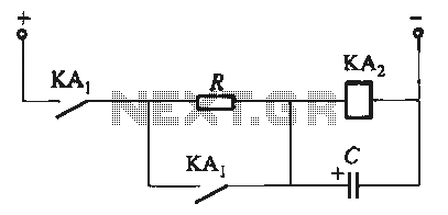
To fulfill the requirements of a control loop, it is often necessary to utilize an electromagnetic relay or a transistor relay to either accelerate or delay an action, thereby forming a circuit designed for acceleration or delay. The circuit...
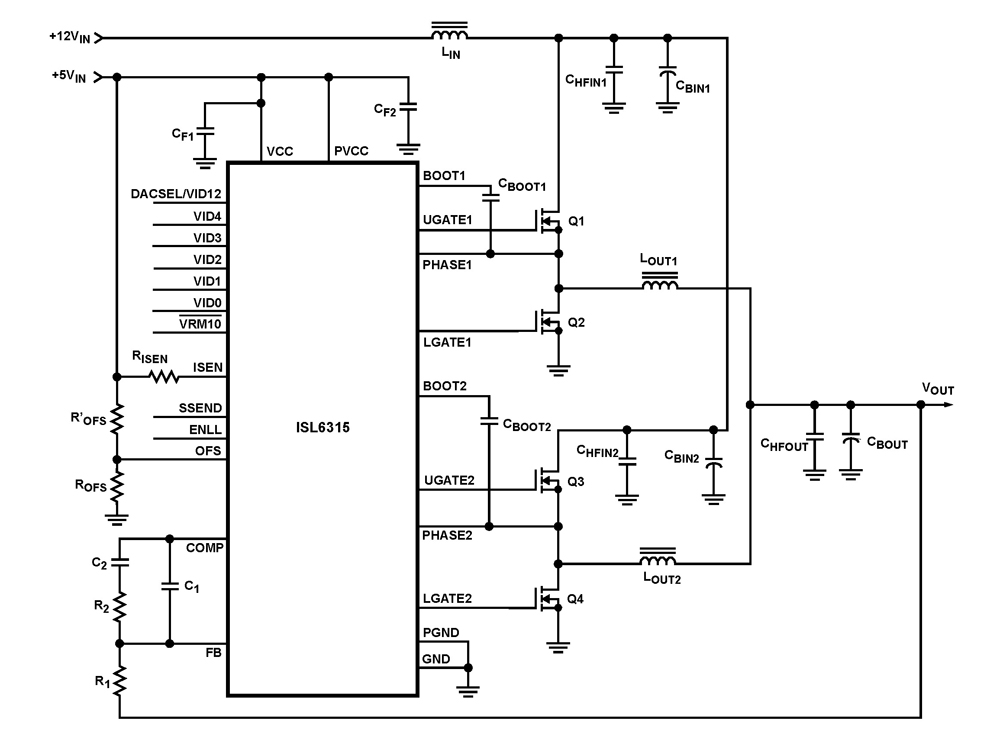
The ISL6315 two-phase PWM control integrated circuit (IC) offers a precise voltage regulation system capable of handling advanced loads ranging from 60A to 80A. Multiphase power conversion represents a significant shift from traditional single-phase converter configurations, which are increasingly...
The doorbell button was replaced with a lighted version, but the chime continued to sound after the button was pressed. These lighted buttons incorporate an incandescent bulb in parallel with the button, a component that has been modified in...
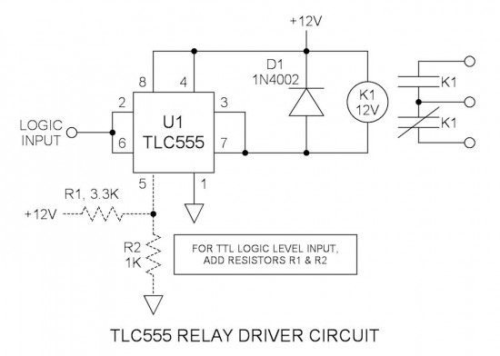
Many integrated circuits possess undocumented features or capabilities. One such example is the TLC555, which can sink a 100mA load down to 1.28V at its output (pin 3). The open-drain transistor reset (pin 7) can also sink 100mA to...
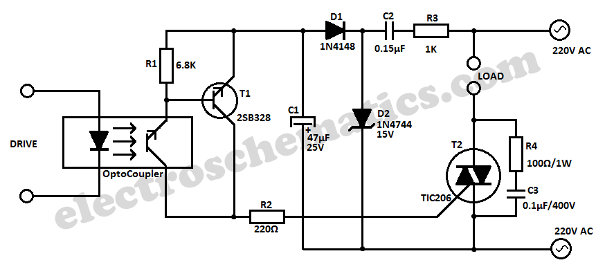
This simple 220V power interface is designed for monitoring electrical equipment and devices using a computer. The interface only detects whether the monitored device is powered on or off. A key feature of this circuit is the galvanic isolation...
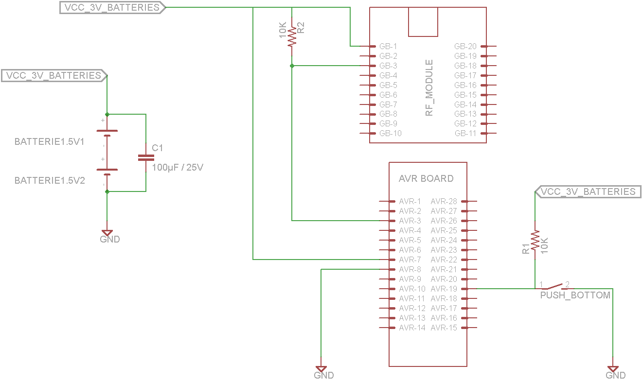
This tutorial demonstrates concepts for creating a lamp with dual actuation. The lamp can be controlled through a parallel switch or by a relay that is managed using an RF module based on the ZigBee protocol (IEEE 802.15.4). The...