
Replacing the driver board in an old-school door chime

The described circuit involves a doorbell system where the traditional button has been substituted with a lighted variant. This modification introduces an incandescent bulb connected in parallel with the button mechanism. When the button is pressed, it not only completes the circuit to activate the chime but also illuminates the bulb.
The issue observed, where the chime continues to sound after the button is released, suggests a potential design flaw or misconfiguration in the circuit. Typically, a standard doorbell circuit consists of a transformer, a chime, and a momentary switch (the button). When the button is pressed, it allows current to flow from the transformer to the chime, producing sound.
In this case, the inclusion of the incandescent bulb in parallel may create a path that keeps the circuit closed even after the button is released. The bulb, when energized, could be causing a feedback loop or a delay in the circuit returning to its open state, maintaining the chime's operation.
To resolve this issue, it is advisable to review the circuit design. One potential solution is to incorporate a relay or a capacitor that can momentarily hold the circuit closed but will eventually open after a short delay, allowing the chime to stop once the button is released. Additionally, ensuring that the button itself is a momentary switch is crucial, as a latching switch could also lead to continuous chime activation.
Overall, careful analysis of the circuit components and their configuration is necessary to ensure proper operation of the lighted doorbell button without unintended chime activation.replaced their doorbell button with one that lights up and found that the chime wouldn`t stop sounding after the button was pushed. These lighted buttons use an incandescent bulb in parallel with the button (a piece of hardware we`ve hacked in the past)..
🔗 External reference
Related Circuits
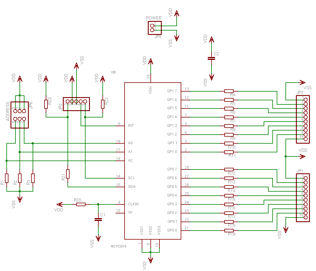
This is a simple, programmable, autonomous and extensible LED matrix with the possibility of being controlled by a computer using a RS232 connection. Its basic modules are the Controller Board, the I/O Port expander boards and the LED matrix...
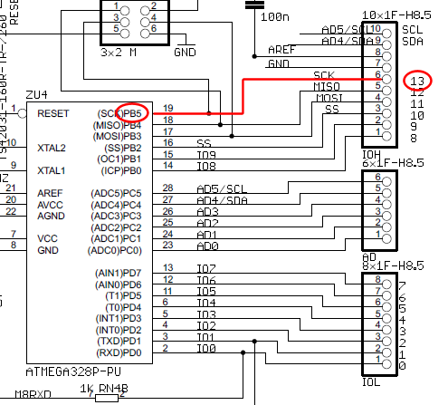
The wire connected to the 5V pin is linked to the positive pins of the breadboard, which are not connected to any other components. There are no additional connections on the positive column. While this may seem like a...

Assume first that SCR1 is on and SCR2 is off, allowing capacitor CI to be fully charged, with its LMP2 end positive. The state of the circuit can be altered by pressing switch S2. When SCR2 turns on, it...
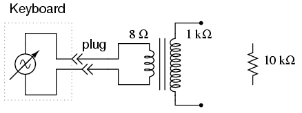
An electronic musical keyboard serves as a source of variable-frequency AC voltage signals. It is not necessary to purchase an expensive keyboard; a model with at least a few dozen voice selections (such as piano, flute, harp, etc.) is...

This circuit provides a simple and effective method for driving fluorescent lamps using a 12 V power supply. The circuit consists of an oscillator, a MOSFET switch, and a step-up transformer to power the fluorescent lamp. The TLC 555...

The GLMDPCB motion detector board is a double-sided etched, screened, and drilled printed circuit board designed for the GLMDA motion detector circuit illustrated in the schematic below. The circuit can be constructed in its entirety or in part. For...