
Delaying the release of DC relay circuit

The circuit design outlined involves the use of capacitive components to manage the timing characteristics of relay operations. The relay serves as an electromechanical switch that can be activated by an electrical signal, with the timing of this activation and subsequent deactivation being critical in control applications. The capacitor in the circuit charges through the relay coil, and this charging process influences the timing of the relay's activation.
When the relay is energized, the capacitor begins to charge, and the time taken for the voltage across the capacitor to reach a specific threshold determines how quickly the relay pulls in. Conversely, when the relay is de-energized, the capacitor discharges through the relay coil, introducing a delay before the relay releases. This delay is essential in applications where immediate deactivation could lead to undesirable outcomes, such as mechanical shock or electrical transients.
The equation provided for estimating the maximum time delay incorporates both the resistance of the circuit and the capacitance of the capacitor. It is important to note that the total resistance (R) includes both the circuit resistance (R) and the resistance of the relay coil (RL), which together influence the charging and discharging rates of the capacitor. The capacitance (C) is a critical parameter, as it directly affects the time constant of the circuit, which is defined as τ = R × C.
In practical applications, selecting the appropriate values for R and C allows for fine-tuning of the delay characteristics to meet specific operational requirements. This flexibility is beneficial in various control systems, ranging from industrial automation to consumer electronics, where precise timing is crucial for reliable performance.In order to meet the needs of the control loop, often require electromagnetic relay or transistor relay to accelerate or delay action, from action to constitute accelerate or delay circuit. Circuit shown in Figure 6-23. These types of circuit is the use of a capacitor charging and discharging of the relay coil to delay the release time Ran. Figure 6-23 (a) ~ (c) is the instantaneous pull, delayed release circuit; Figure 6-23 (d) to pull delay, release delay circuit.
The maximum time delay relay may be estimated by the following equation: t = 0 85R.. CX10-6 (s) where R: - the total circuit resistance, R: = R + RL, 0; R resistance, 0; foot L- relay coil resistance, N; C capacitance, pF.
Related Circuits
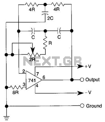
The quality of the sine wave depends on how closely the components in the twin-T network are matched in the operational amplifier's feedback loop. The twin-T network is a type of filter circuit commonly used in audio applications, signal processing,...
The generator consists of an integrator functioning as a ramp generator and a threshold detector with hysteresis acting as a reset circuit. The integrator has been previously described and does not require further elaboration. The threshold detector operates similarly...
An FM radio generates an interference signal that can be detected on another FM radio tuned 10.7 MHz higher than the original. A 50 kΩ potentiometer is used to adjust the modulation level to its maximum without introducing distortion....
This circuit can be used for detecting infrared light; for example, it is utilized for detecting infrared band light signals in a spectrophotometer. The amplifier output voltage Vo is given by the formula Vo = Is·Rd·Rf/Ri, where Is is...
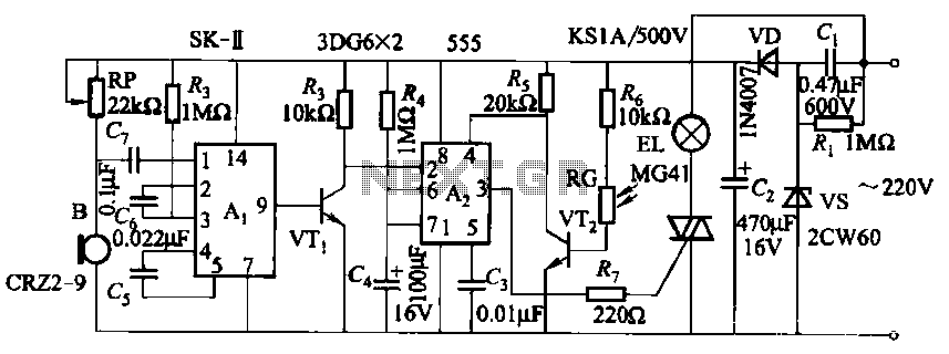
This circuit utilizes a dedicated voice integrated circuit (AI) of the SK type, which incorporates an internal bistable multivibrator and three inverting amplifiers. The 555 integrated circuit (IC) A2 is employed for delay control. The described circuit is designed to...
A varying brightness AC lamp circuit utilizes a silicon-controlled rectifier (SCR) to gradually adjust the intensity of a 120-volt light bulb by controlling the duration of AC line voltage applied to the lamp during each half cycle. The circuit...