
Motion (Motor) Control Servo System Block Diagram
 Control Servo System Block")
Automated systems utilizing closed-loop feedback mechanisms are designed to enhance precision and responsiveness in motion control applications. A typical servo system within these frameworks comprises several key elements: a controller, a feedback sensor, an actuator, and a reference input.
The controller is responsible for processing the error signal, which is the difference between the desired position and the actual position as reported by the feedback sensor. This error signal is then used to adjust the actuator's position accordingly. The feedback sensor, often a rotary encoder or a linear position sensor, continuously monitors the output of the actuator to ensure that it aligns with the input command.
The actuator, which can be an electric motor or a hydraulic cylinder, converts the control signals from the controller into physical motion. The reference input serves as the target position or speed, which the system aims to achieve.
In a closed-loop system, the continuous feedback loop allows for real-time adjustments, enhancing stability and accuracy. This configuration is particularly advantageous in applications such as robotics, CNC machinery, and automated assembly lines, where precise control over movement is critical.
The block diagram representation of such a system typically illustrates the interconnections between these components, highlighting the flow of information and control signals. This schematic serves as a vital tool for understanding the operational dynamics of modern automated systems and aids in the design and troubleshooting processes.Below is a block diagram of a modern automated systems incorporate closed-loop feedback for motion control. They typically include a servo system that consist. 🔗 External reference
Related Circuits
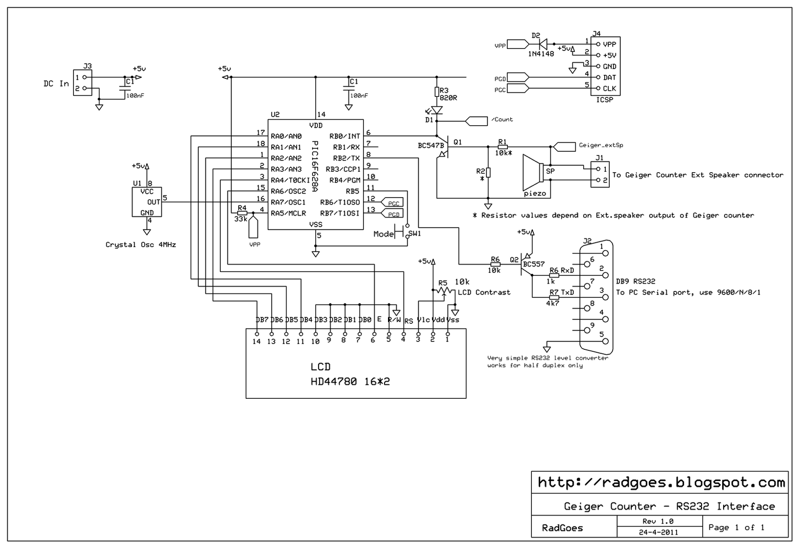
A selection of reasonably priced ex-army radiation detectors was discovered at an army surplus store. Among them was a Frieseke & Hoepfner FH40T Geiger counter, equipped with a FHZ76V energy-compensated Geiger-Mueller tube, which is sensitive to gamma (³) and...
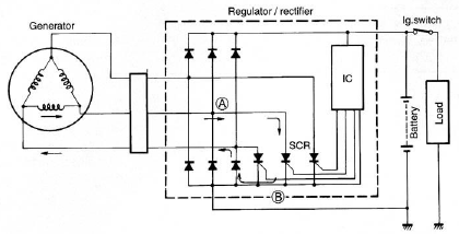
The circuit of the Suzuki GSX1300 Hayabusa charging system consists of a generator, a regulator/rectifier unit, and a battery. The alternating current (AC) generated by the generator is rectified by the rectifier to produce direct current (DC), which is...
The following circuit illustrates the AC Motor Speed Controller Kit - K2636 Circuit Diagram. Features include standard dimmer functionality, utilizing carbon components. The AC Motor Speed Controller Kit - K2636 is designed to regulate the speed of AC motors, making...
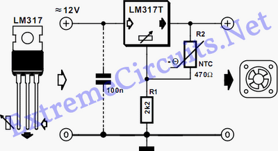
The fan operates continuously in many PCs, which may not always be necessary. A straightforward controller circuit can adjust the fan speed based on demand. This not... A fan speed controller circuit can significantly enhance the efficiency of cooling systems...
The Controller Area Network (CAN) data rate ranges from 10 kbit/s to 1 Mbit/s, with recommended distances of 40 to 1000 meters using two twisted pairs—one for data and the other for power and ground. Up to 110 nodes...
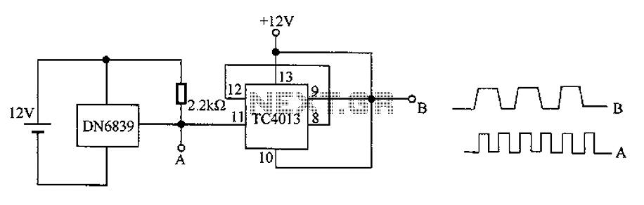
The circuit utilizes the integrated Hall element DN6839 for frequency division. It detects a magnetic field through the pulsating DN6839, generating a pulse waveform. The circuit is designed for applications involving very high-frequency pulsating magnetic fields. It employs the...