
Motor Control Circuit of LM339

The motor control circuit operates by employing the LM339, a quad comparator, to analyze the input control signal. When the signal is high, it triggers comparators A and A3, which in turn activate a power amplifier circuit formed by operational amplifier A4 and transistors VT5 and VT6. This configuration allows for efficient control of the motor M, ensuring it receives the necessary power to operate.
The inclusion of capacitance C1 serves a crucial role in the circuit by integrating the armature current, providing feedback to stabilize the motor's operation. The reset function of C1 is vital for maintaining accurate monitoring of the armature current, preventing overload conditions by ensuring that the current does not exceed safe operating limits.
The overall design emphasizes reliability and responsiveness, making it suitable for applications requiring precise motor control. The use of comparators allows for quick adjustments to the motor's power based on real-time input signals, while the feedback mechanism helps in maintaining consistent performance under varying load conditions. This circuit is ideal for automation and robotics where motor control precision is essential.The above picture is the motor control circuit composed of LM339 etc.When the input control signal is high PWL,comparator A and A3 make power amplifier conduct composed of A4,VT5 and VT6 and it drives motor M.At the same time,comparator also outputs and removes the armature current integral capacitance C1 reset.The armature current monitors the current e.. 🔗 External reference
Related Circuits
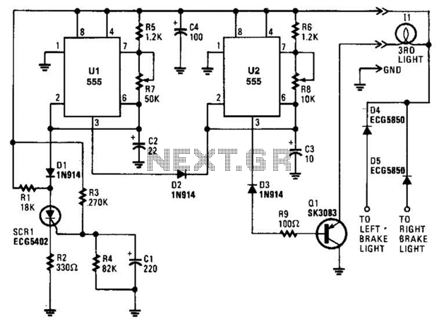
When power is first applied, three events occur: the light-driving transistor (Q1) is activated due to a low output from U2 at pin 3; timer U1 begins its timing cycle, with the output at pin 3 going high, which...
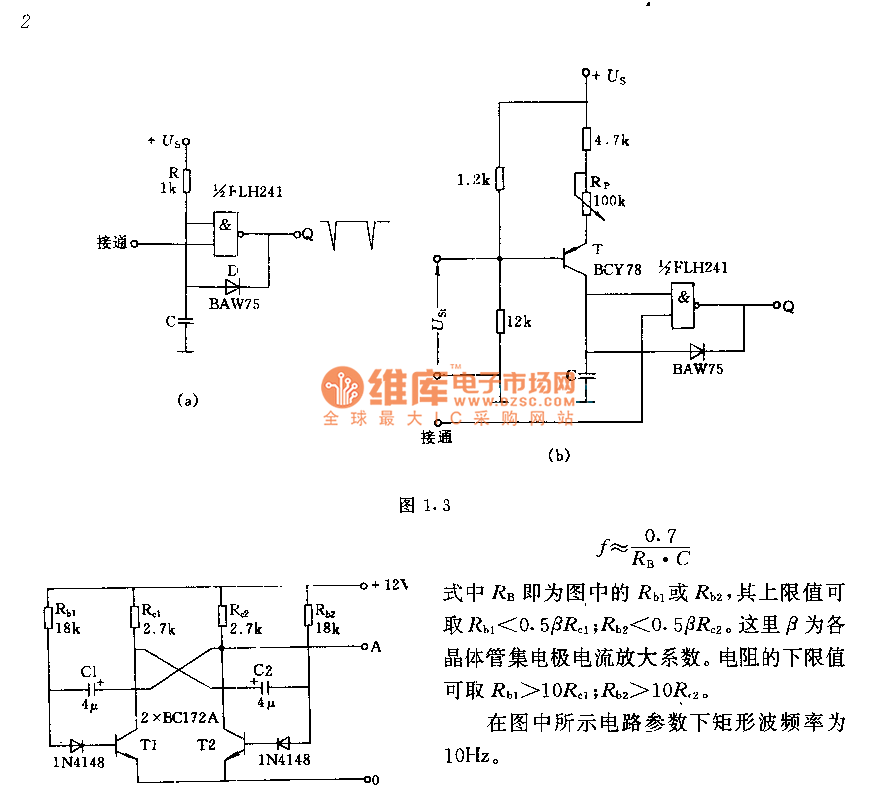
The circuit consists of two components whose parameters and models are designed to simultaneously generate a rectangular wave with a duty cycle of 1:1. The frequency is defined by the equation f = 0.7/(RB * C), where RB refers...
This DC drill speed controller circuit allows for the adjustment of the rotational speed of a drilling machine. A mini-drill machine is always... This circuit utilizes a pulse-width modulation (PWM) technique to control the speed of a DC motor, which...
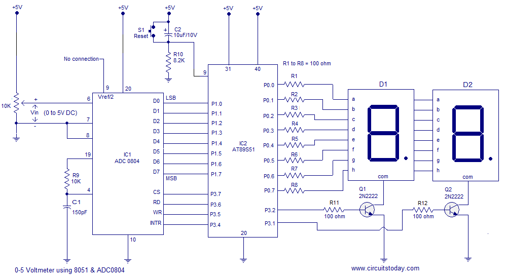
A simple 0-5 digital voltmeter utilizing the 8051 (AT89S51 microcontroller) is presented, accompanied by a circuit diagram and assembly language (ASM) code. This digital voltmeter is designed for straightforward voltage measurement. The circuit employs an AT89S51 microcontroller, which serves as...
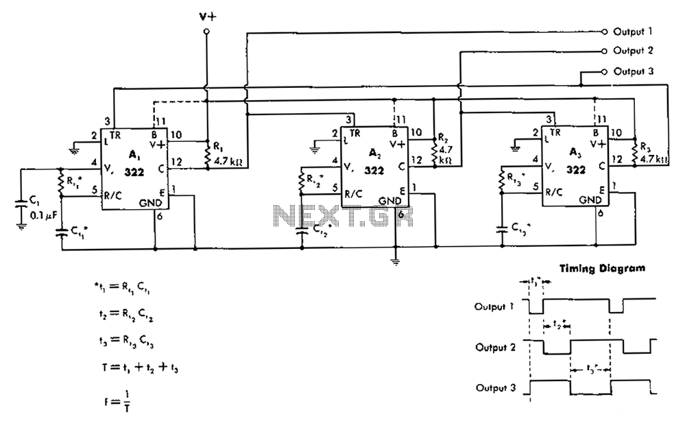
The 322 monostable multivibrator is configured in a cross-connected manner. When operating under non-steady state conditions with the oscillator Unicom, it generates a continuous timing cycle, as illustrated in the accompanying figure. T represents the total time period of...
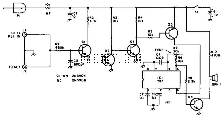
For use with low-power transmitters that require a positive keying voltage. The transistors Q1, Q2, and Q3 are configured as a switching amplifier. When the key is pressed, the collector of Q3 is pulled to ground, which activates Q5...