
Multiple switches on Arduino analog pin schematic
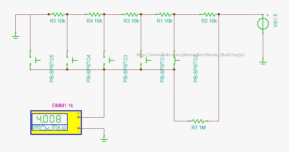
The circuit design involves connecting a 5-way joystick or button module to an Arduino microcontroller through a single analog input pin. The joystick's multiple states are represented by varying voltage levels, which correspond to the different positions of the joystick. This design simplifies the input method, allowing for multiple states to be detected without requiring multiple digital pins.
In this configuration, each state of the joystick generates a specific voltage: 0V when released, and increasing voltages (1V to 5V) as the joystick is moved in different directions. The addition of a 1 MΩ resistor (R7) serves as a pull-down resistor, ensuring that the voltage is stable when all switches are open. This configuration is particularly useful in applications where power consumption needs to be minimized, such as in battery-operated devices, although in this case, the design does not prioritize battery operation.
For further refinement, the internal pull-up resistors available on the Arduino can be enabled. This alternative approach eliminates the need for external resistors by using the microcontroller's built-in features to maintain a defined voltage level when switches are not engaged. This can enhance reliability and reduce component count in the circuit.
Overall, the implementation of a 5-way joystick connected to a single analog pin provides an efficient solution for input handling in various electronic projects, facilitating user interaction while conserving resources.Connect a 5 way button/joystick to an Arduino using a single analog pin and wanted to quickly simulate it to verify my calculations before I went and soldered everything. The voltages for the six states are 0, 1, 2, 3, 4, 5. The 4V being shown in the photo is because one of the switches is pressed. I solved the problem of the all switches open state voltage by adding in the 1Mohm R7, which was okay for me since
I wasn`t making something battery operated. Some people prefer to turn on the internal pull-up on the chip.
Related Circuits
Constantly changing light and sound analog controller circuit 07 The circuit described is an analog controller designed to modulate light and sound in a dynamic manner. This circuit utilizes various electronic components to create an interactive experience where both light...
The schematic for an infrared burglar alarm circuit is depicted in Figure 1. The infrared transmitter operates as a multivibrator with an oscillation frequency of 40 kHz, utilizing the NE555 integrated circuit (IC2), along with resistors R1 and R2...
Two low voltage, low power zeners are used to control electronically the level of an audio signal. The attenuation range is from 6 to 58dB for an input current from 0.042 to 77mA corresponding to a control voltage from...
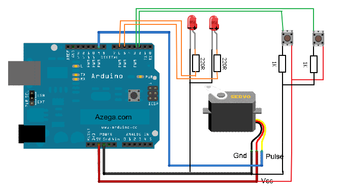
A servo motor is programmed to be controlled by two buttons; one button rotates the servo to the left and the other button rotates it to the right. When the servo is in motion, an LED corresponding to the...
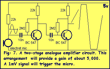
This chapter shows how to connect an analogue signal to a PIC. An analogue signal is similar to a sine wave and is generally less than 5v (5,000mV) in amplitude. Low-level signals are generally expressed in mV, to make...
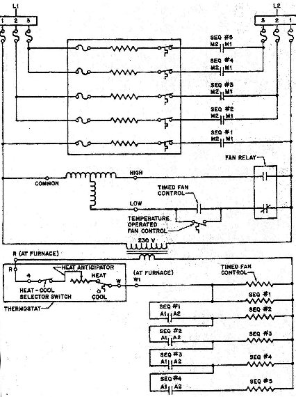
This diagram allows for easy identification of test points related to Applied Voltage and Potential Voltage. For instance, by isolating one of the heating elements, an N.O. (Normally Open) switch can be observed wired in series with it. The...