
Constantly changing light and sound analog controller circuit 07

The circuit described is an analog controller designed to modulate light and sound in a dynamic manner. This circuit utilizes various electronic components to create an interactive experience where both light intensity and sound output can be adjusted in real-time. The core of the design typically includes operational amplifiers, resistors, capacitors, and possibly transistors to facilitate the modulation processes.
In this circuit, light modulation may be achieved through the use of light-emitting diodes (LEDs) or incandescent bulbs, which can be controlled by varying the voltage supplied to them. The sound output could be generated using a piezoelectric speaker or a small audio amplifier, where the frequency and amplitude of the sound can be altered based on the input signals from the controller.
To implement the constantly changing aspect, the circuit may incorporate a feedback mechanism, such as a light-dependent resistor (LDR) or a microphone, which detects changes in ambient light or sound levels. The feedback is processed through the operational amplifiers, which adjust the output signals accordingly. Additionally, the inclusion of a microcontroller can enhance the circuit's capabilities by allowing programmed patterns of light and sound changes, enabling more complex interactions.
Overall, this circuit exemplifies a versatile approach to creating an engaging environment through the integration of light and sound, demonstrating the principles of analog control in electronic design.Constantly changing light and sound analog controller circuit 07
Related Circuits
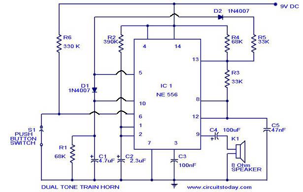
A dual-tone model train horn/sound generator/simulator circuit can be created using two NE 555 timers connected in cascade. However, the circuit diagram presented is designed with the NE 556 integrated circuit, which essentially comprises two 555 timers in a...
Power pulse circuit using LM350 and NE555. This circuit can be used to drive lamps, power LEDs, DC motors, etc. Adjust R5 for output amplitude and R1 for output power. The LM350 is an adjustable 3-terminal voltage regulator. The power...
This complete high quality, low noise 5-BAND GRAPHIC EQUALIZER circuit is based around Monolithic Linear integrated circuit LA3600 manufactured by SANYO. This circuit is very easy to build and has good Quality. You can use it with Portable component...
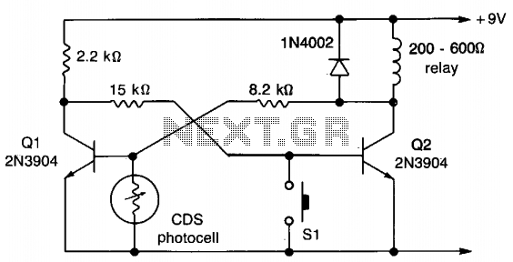
This circuit employs a flip-flop configuration utilizing Q1 and Q2. Under normal conditions, Q1 is heavily conducting. When light is detected by the CDS photocell, the bias on Q1 decreases, resulting in its cutoff, which activates Q2 and removes...
This is a simple, cheap device that can be connected to any serial port to control most components that have infrared remote controls. I designed and built it on a solderless breadboard in 1991. In 1992 I wrote a...
This circuit utilizes the AD639 universal trigonometric function generator from Analog Devices to transform a triangle waveform, which serves as the fundamental waveform of the VCO, into a low-distortion sine wave. By operating the AD639 in its frequency tripler...