
Op-Amp Based PWM Circuit
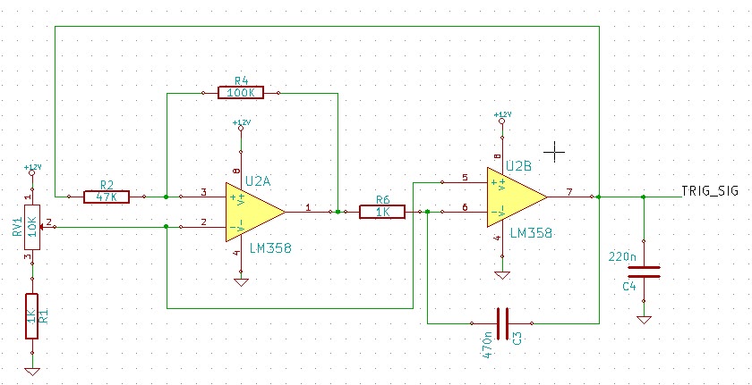
The circuit's core functionality revolves around the generation of a PWM signal, which is essential for controlling power delivery to devices such as motors or solenoids. The LM358 op-amps are configured to operate in a comparator mode, where the output signal's duty cycle can be adjusted by varying the reference voltage through the potentiometer RV1. This allows for precise control over the PWM signal, making it suitable for applications requiring variable speed or power adjustments.
The low-pass filter composed of resistor R8 and capacitor C4 plays a critical role in stabilizing the output signal. By filtering out high-frequency noise, the filter ensures that the PWM signal maintains a clean waveform, which is particularly important when driving inductive loads such as solenoids. The smoothing effect provided by this filter can prevent erratic behavior in the actuator, leading to more reliable operation.
In terms of circuit layout, careful attention should be paid to the placement of components to minimize noise and interference. The use of a single supply operational amplifier simplifies the power requirements, allowing the circuit to be powered from a straightforward DC source, which aligns with the design's goal of ease of repair and accessibility.
Overall, this circuit exemplifies a practical solution for generating PWM signals without the complexity of microcontrollers, making it ideal for applications in environments where simplicity and reliability are paramount.This circuit uses the LM358 operational amplifiers (or any single supply op amp) to generate a pulse-width modulated signal. In most cases, I would just use a microcontroller to generate PWM signals. Unfortunately, the circuit was designed for a local marine repair company which requested the circuit to be easily repairable and built without the n
eed of an external programmer, etc. Since this is rail to rail design, a reference voltage (changed using potentiometer RV1`) has to be placed on the non inverting pins of the U2A` op-amp. The R8 resistor and C4 capacitor acts as a low pass filter which will filter some a the high frequency spikes and smooth the transition peak.
I believe this portion of the circuit is optional but I just added it to make the triangle signal looks nice on my oscilloscope. Unfortunately, I have forgotten to take a picture of the completed PCB board and the working prototype.
However, I did took a picture of the 3 Amp solenoid actuator which was tested on. 🔗 External reference
Related Circuits
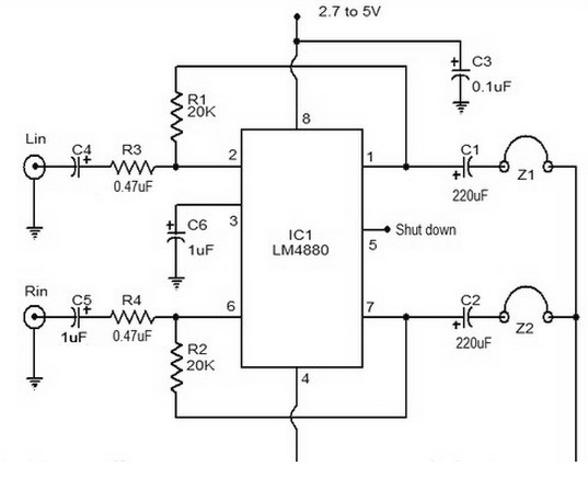
The LM4880 is a dual audio HiFi amplifier integrated circuit from National Semiconductor. This headphone amplifier circuit is specifically designed to produce high-quality audio output with a minimal number of components. The LM4880 integrated circuit is capable of delivering...
This circuit detects AC line currents of approximately 250mA or greater without establishing any electrical connections to the line. The current detection occurs through an inductive pickup (L1) constructed from a 1-inch diameter U-bolt wound with 800 turns of...
The motor vehicle currently represents a no-emission automotive solution, serving as a green means of transportation that is expected to significantly impact human society in the 21st century. The direct-flow brushless electric machine has emerged as a leading technology...
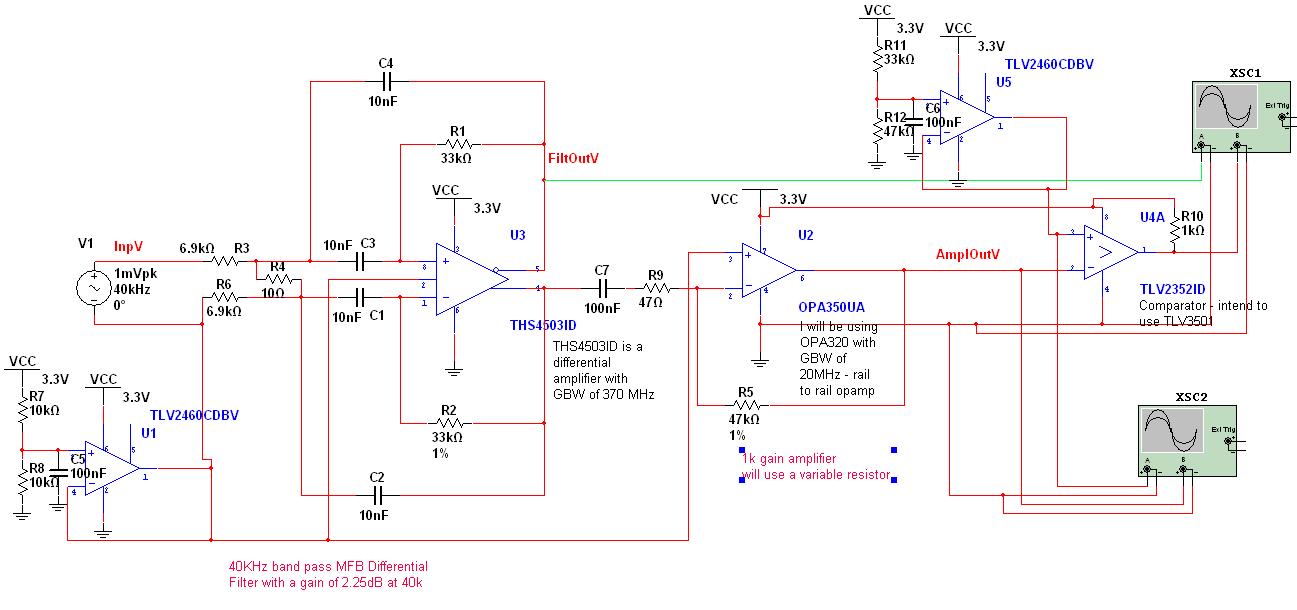
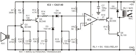
A circuit has been designed to detect the duration of an ultrasonic pulse as it travels a certain distance. The input signal is sourced from a 40 kHz ultrasonic receiver. The first stage consists of a 40 kHz band-pass...
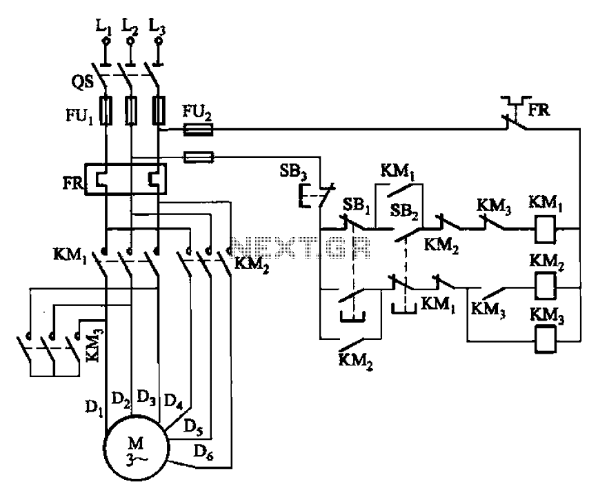
The circuit depicted in Figure 3-96 features a low-speed operation button (SBz), a high-speed operation button (SBi), and a stop button (SB3). In this configuration, a motor is connected in such a way that when the low-speed button is...
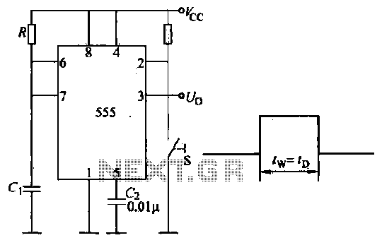
Introduction to the circuit schematic depicted in Figure 3-3. In this configuration, the 555 timer is utilized in a monostable mode, typically activated by a normally open push button switch. The circuit operates in an S-shaped state, where the...