
PCB designing using KiCAD Tutorial
The astable multivibrator circuit using the 555 timer IC is a fundamental electronic configuration that generates a continuous square wave output without requiring any external triggering. The 555 timer, a versatile integrated circuit, can be configured in various modes, and the astable mode is particularly useful for applications such as clock pulses, LED flashers, and tone generation.
In the astable configuration, the 555 timer operates between two states: high and low, continuously switching between them at a frequency determined by external resistors and capacitors. The circuit typically includes two resistors, R1 and R2, and a capacitor, C1, connected to the 555 timer in the following manner:
1. **Connections**:
- Pin 1 (GND) is connected to the ground.
- Pin 8 (VCC) is connected to the positive supply voltage, typically between 4.5V to 15V.
- Pin 2 (Trigger) and Pin 6 (Threshold) are connected together and also connected to the junction of R2 and C1.
- Pin 3 (Output) provides the square wave output.
- Pin 4 (Reset) is connected to VCC to disable the reset functionality.
- Pin 5 (Control Voltage) is often connected to ground through a capacitor (typically 0.01 µF) to filter noise.
- Pin 7 (Discharge) is connected to the junction of R1 and R2.
2. **Operation**:
- When power is applied, C1 begins charging through R1 and R2. The voltage across C1 increases until it reaches 2/3 of VCC, at which point the 555 timer switches its output to low, causing C1 to discharge through R2 and pin 7 until it drops below 1/3 of VCC. This cycle repeats, generating a continuous square wave.
3. **Frequency Calculation**:
- The frequency (f) of the output square wave can be calculated using the formula:
\[
f = \frac{1.44}{(R1 + 2R2) \times C1}
\]
- The duty cycle, which determines the ratio of the high state to the total period, can also be calculated, typically resulting in a duty cycle less than 50% due to the configuration of the resistors.
This simple astable multivibrator circuit demonstrates the basic principles of timing and oscillation in electronics, providing a practical application for the 555 timer IC in various projects.Here is a quick guide, which will help you to get started off with kiCAD. In this tutorial we will be considering a simple astable multivibrator circuit using 555 timer IC 🔗 External reference
Related Circuits
For hobbyists or professional electronic engineers engaged in various electronic experiments, troubleshooting, or testing, it is essential to provide a wide range of variable options. In electronic engineering, the ability to manipulate and measure a wide range of variables is...
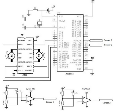
The electronic schematic of the Light Detector Robot can be divided into three main components: the sensor, the microcontroller, and the DC motor driver. The light sensor utilized in this design is a Light Dependent Resistor (LDR), which alters...
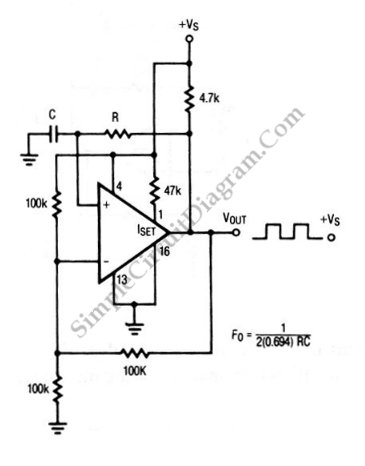
The circuit depicted in this schematic diagram is a square-wave oscillator circuit. The primary component of this oscillator circuit is the LP165/365 comparator. The square-wave oscillator circuit utilizes the LP165/365 comparator to generate a continuous square wave output. The...
This circuit is designed for children's entertainment and can be installed on bicycles, battery-powered cars, motorcycles, as well as models and various games and toys. When switch SW1 is positioned as indicated in the circuit diagram, it generates the...
A digital integrated circuit simplifies the response process significantly. The diagram illustrates a circuit comprising four responder groups. The digital integrated circuit described serves as a crucial component in various electronic systems, primarily focusing on enhancing response efficiency. It comprises...
The interval between rings can be adjusted by changing the value of the 1 Meg resistor. A 70 volt, 30 Hz ringing voltage is generated from the 120 volt side of a small 12.6 VAC power transformer (Radio Shack...