
Square Wave Oscillator using Comparator/Op-Amp

The square-wave oscillator circuit utilizes the LP165/365 comparator to generate a continuous square wave output. The operation of this circuit relies on the feedback mechanism that establishes a stable oscillation frequency. The comparator serves as the central element, comparing two input voltages: a reference voltage and the voltage derived from the output through a resistor-capacitor (RC) network.
In typical configurations, the circuit includes a resistor (R) and capacitor (C) connected in series, which determines the timing characteristics of the oscillation. The charging and discharging of the capacitor through the resistor create a time delay that influences the frequency of the output waveform. The output of the comparator toggles between high and low states as the voltage across the capacitor reaches the threshold levels set by the reference voltage.
The frequency of oscillation can be calculated using the formula \( f = \frac{1}{T} \), where \( T \) is the time period of one complete cycle. The time period is influenced by the values of the resistor and capacitor, and it can be adjusted to achieve the desired frequency. The output waveform is typically a symmetrical square wave, characterized by equal high and low durations.
For practical applications, additional components such as diodes or additional comparators may be incorporated to shape the waveform or enhance stability. The design may also include provisions for power supply decoupling to ensure reliable operation in various environments. Overall, the square-wave oscillator circuit based on the LP165/365 comparator is a versatile and widely used configuration in various electronic applications, including clock generation, signal modulation, and waveform generation.The circuit shown in this schematic diagram is a square-wave oscillator circuit. The main component of this oscillator circuit is LP165/365 comparator. As.. 🔗 External reference
Related Circuits
This circuit is a crystal oscillator that operates at a frequency of 3.5 MHz. The crystal oscillator circuit utilizes a quartz crystal resonator to generate a stable frequency output. The primary components typically include the crystal, an amplifier (often a...
This simple circuit amplitude-modulates a single tone to approximate the echo effect similar to that produced by sonar apparatus. Individuals familiar with sonar-equipped vessels may recognize the imaginative similarities between this basic scheme and actual sonar technology. This circuit...
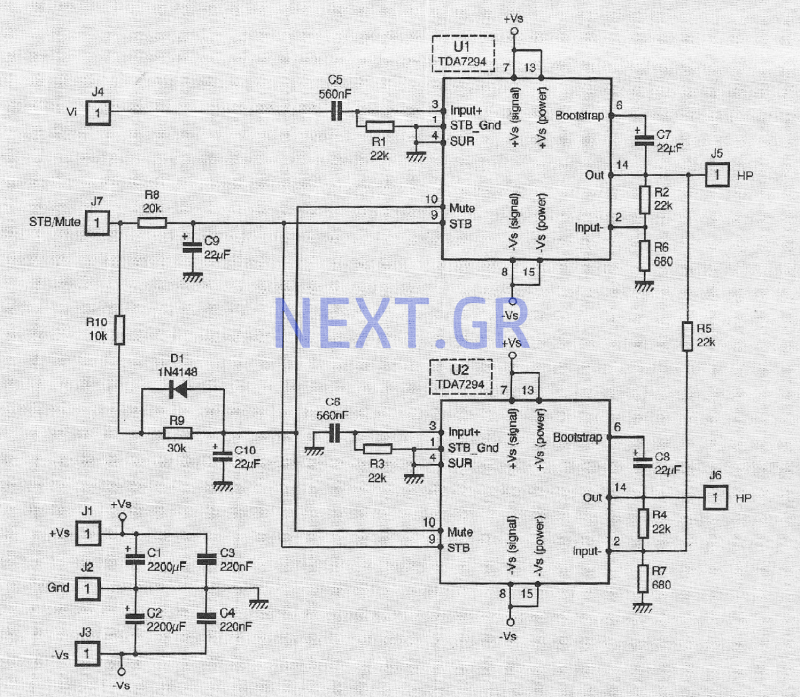
The TDA 7294 from T-MICROELECTRONICS is a monolithic integrated circuit housed in a "Multiwatt 15" package, primarily designed for use in Class AB amplifiers for high-fidelity applications, including stereo systems, active speakers, and television receivers. Its large feed area...
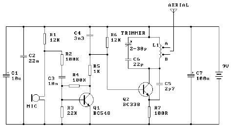
The tuned coil L1 has two output tap points for the antenna connection, labeled "A" and "B." Both outputs are low-level, allowing the user to select between a stable low range or a more unstable but higher range. Tap...
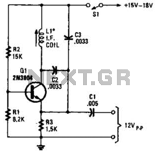
A simple oscillator for intermediate frequency (IF) alignment at 455 kHz can be useful in field testing or in scenarios where a standard signal generator is available. The inductor (L1) should resonate at the desired output frequency with the...
The beat frequency oscillator (BFO) is essential for receiving continuous wave (CW) signals. Since CW signals lack an audio modulation component, it is necessary to introduce one. The functions of the RF amplifier, mixer, local oscillator, and IF amplifier...