
Digital integrated circuits using CMOS circuit Responder

The digital integrated circuit described serves as a crucial component in various electronic systems, primarily focusing on enhancing response efficiency. It comprises four distinct responder groups, each designed to perform specific functions within the overall circuit architecture.
The responder groups may be configured to handle different input signals, process these signals, and provide outputs that can be utilized for further actions within the system. Each group typically includes a combination of logic gates, flip-flops, and multiplexers, which work together to ensure accurate and timely responses to input changes.
In the schematic, each responder group can be visualized as a modular unit, allowing for flexibility in design and scalability. The interconnections between these groups are critical, often involving bus systems or dedicated lines that facilitate communication and data transfer. The use of digital logic levels ensures that the circuit operates with high reliability and minimal noise interference.
Power supply considerations are also paramount in the design of such circuits. Each responder group may require a stable voltage source, often provided by a regulated power supply circuit integrated into the overall design. Additionally, decoupling capacitors are typically employed to filter out voltage spikes and maintain stability during operation.
Overall, this digital integrated circuit design exemplifies modern approaches to circuit simplification while maintaining functionality and performance, making it suitable for a wide range of applications in digital electronics.Digital integrated circuit enables the answer is greatly simplified. The picture shows four Responder group circuit.
Related Circuits

The original smoke alarm circuit has several issues that have left hobbyists and students dissatisfied. Instead of trying to resolve its numerous problems, an updated version has been created using the well-known LM741 op-amp. This new design is simpler,...
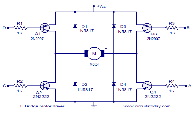
The circuit presented is a simple H-bridge motor driver circuit utilizing commonly available components. An H-bridge is an efficient method for driving motors and is widely used in various electronic projects, particularly in robotics. The circuit illustrated is a...
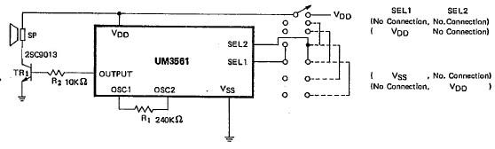
This siren alarm circuit diagram utilizes the specialized integrated circuit (IC) UM3561, which is a low-power CMOS large-scale integration (LSI) device specifically designed for such applications. The UM3561 incorporates all necessary components, including an oscillator, selector circuits, and programmed...

This circuit is a simple connection delay lamp circuit. When the lights are turned on and the switch is pressed, the power supply is activated. The capacitor charges rapidly, causing the thyristor (VT) to open, which in turn lights...

This 4 1/2-digit DVM circuit is built around a Maxim ICL7129ACPL A/D converter and LCD driver. An ICL8069 CCZR 1.2-V band-gap reference diode is used for a voltage reference. S2a-b-c select one of four ranges up to 200 V...

An H-bridge circuit has been developed utilizing four floating gate drivers and four insulated gate bipolar transistors (IGBTs). The attached schematic illustrates one half of the H-bridge configuration. The circuit operates effectively, but there are additional considerations to address. The...