
PIC Programmer
The uJDM PIC programmer is a compact and efficient circuit used for programming a range of Microchip PIC microcontrollers. It operates through a USB interface, allowing it to connect directly to a computer for programming tasks. The circuit typically includes a few key components: a USB connector, a microcontroller interface, and various passive components such as resistors and capacitors that facilitate programming operations.
The core of the uJDM programmer is a dedicated microcontroller that manages the communication between the computer and the target PIC microcontroller. This microcontroller translates the programming commands from the software running on the computer into the appropriate signals required to program the target device. The circuit is designed to support multiple PIC variants, making it versatile for different applications.
For operation, the programmer connects to the target PIC microcontroller via a set of pins that correspond to the programming interface of the PIC device. These pins typically include Vpp (programming voltage), Vdd (operating voltage), and several data lines for communication. The circuit is powered through the USB connection, which simplifies the setup and eliminates the need for an external power supply.
The schematic of the uJDM PIC programmer will include the necessary connections and component values to ensure reliable operation. It is important to follow the schematic closely to avoid damage to the microcontroller or the programmer itself. Additionally, the programmer's software must be compatible with the target microcontroller to ensure successful programming.
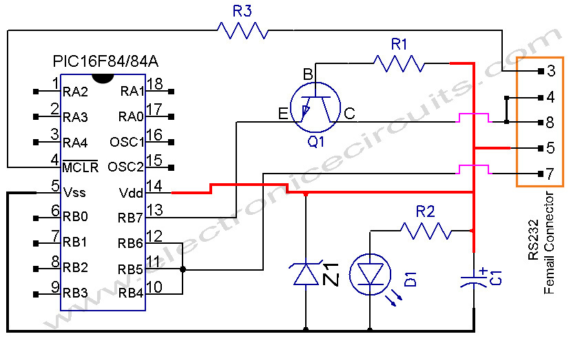
In summary, the uJDM PIC programmer circuit is an essential tool for developers working with Microchip PIC microcontrollers, providing a straightforward and effective method for programming various PIC models.PIC Programmer Circuit diagram Following uJDM PIC programmer circuit is a circuit which suitable to do simple pic16f84, pic16f84A, 16c84,.. 🔗 External reference
Related Circuits
This project will explain how I build my new wattmeter. This watt meter will be able to measure power from 300nW to 30W @ (0-500MHz). This wattmeter is based up on a dummy load of 50 ohm which can...
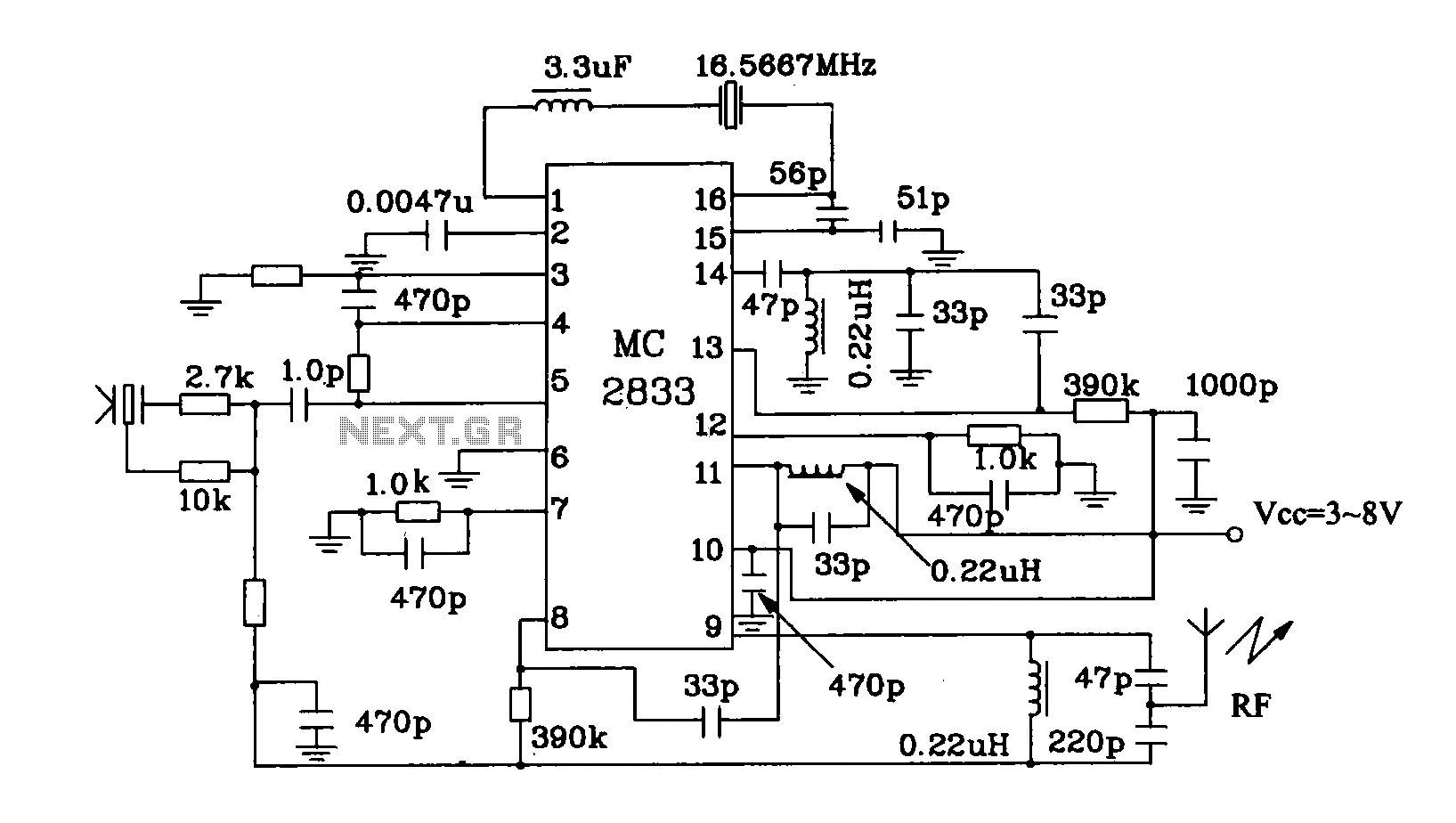
The MC2833 MC2831 radio transmitter dedicated circuit has been enhanced. This circuit is a typical application for radio transmitters, generating a high-frequency signal of 49.7 MHz that is transmitted through the antenna. The MC2833 and MC2831 integrated circuits are designed...
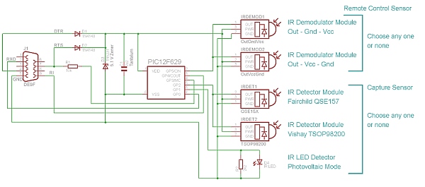
Simple IR capture for multitasking operating systems. The IR Widget captures the infrared signals used by remote controls. It operates in a way that makes it suitable for multitasking environments. The IR Widget is designed to interface with multitasking operating...
Using only 2 capacitors, 3 resistors, 4 seven-segment displays, 1 xtal, 2 switches n.o. and 1 Microcontroller PIC, you can build this Digital Led Clock. You can use common anode or common cathode display, just select the display type....
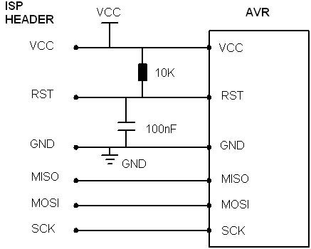
AVR In System Programmer manufactured in the UK by Kanda, a well-known provider of AVR In System Programmers both in the UK and globally. The AVR In System Programmer (ISP) is a specialized device designed for programming AVR microcontrollers directly...
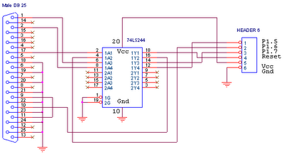
This circuit is designed for use with ATMEL Microcontroller ICs, specifically the AT89Sxx and ATMEGA series. It operates using the MISO, MOSI, SCK, and RESET signals. This circuit serves as a foundational interface for programming and communication with ATMEL microcontrollers,...