
this circuit is isp flash programmer

This circuit serves as a foundational interface for programming and communication with ATMEL microcontrollers, particularly the AT89Sxx and ATMEGA series. The primary signals involved in this circuit are MISO (Master In Slave Out), MOSI (Master Out Slave In), SCK (Serial Clock), and RESET, which are essential for synchronous serial communication.
The MISO line is used to transmit data from the microcontroller to the master device, while the MOSI line carries data from the master to the microcontroller. The SCK line provides the clock signal that synchronizes data transmission between the master and the microcontroller. The RESET line is crucial for initializing the microcontroller, ensuring it starts executing code from the beginning of its memory.
In practical applications, this circuit can be implemented for various purposes, including programming the microcontroller during development or enabling communication between the microcontroller and other devices in an embedded system. The circuit may include pull-up resistors on the RESET line to ensure reliable operation, as well as decoupling capacitors to stabilize the power supply voltage.
Overall, this circuit is integral to leveraging the capabilities of ATMEL microcontrollers, facilitating both development and operational functionality in electronic systems.This circuit is used on the ATMEL Microcontroller IC. However, the circuit is used for Microcontroller AT89Sxx. and ATMEGA xxx if you know about MISO, MOSI, SCK AND RESET 🔗 External reference
Related Circuits
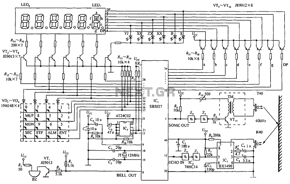
A circuit diagram of an ultrasonic range finder is constructed using a clock with a calendar and the Ultrasonic Ranging IC SB5027. The ultrasonic range finder circuit utilizes the Ultrasonic Ranging IC SB5027, which is designed to measure distances by...
A fluorescent tube is connected in an LC resonant circuit consisting of inductor L2 and capacitor C9. The bidirectional breakdown diode VD4 initiates the starting circuit. When AC power is applied, the gate potential of transistor VT2 increases due...
This circuit is an automatic street light controller. The sensor used to detect changes in light is an LDR (Light Dependent Resistor). The working principle of the LDR is that when exposed to light, its resistance value decreases, while...
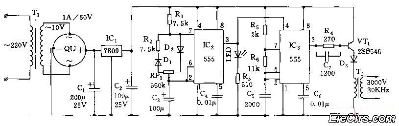
Adjust the RP1 to modify the pulse duty cycle of IC2, which in turn alters the pulse oscillation time of IC3. This regulation allows for the control of ozone generation time, effectively changing the concentration of ozone in the...
The text of the Arduino reference is licensed under a Creative Commons Attribution-ShareAlike 3.0 License. Code samples in the reference are released into the public domain. The Arduino platform is an open-source electronics prototyping environment that enables users to create...
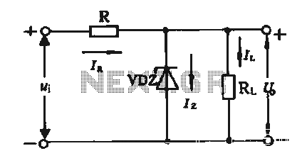
The simple voltage regulator circuit consists of a silicon regulator and a resistor. It is designed to rectify and filter DC voltage, as illustrated in the accompanying figure. The voltage regulator is connected in parallel with the load, and...