
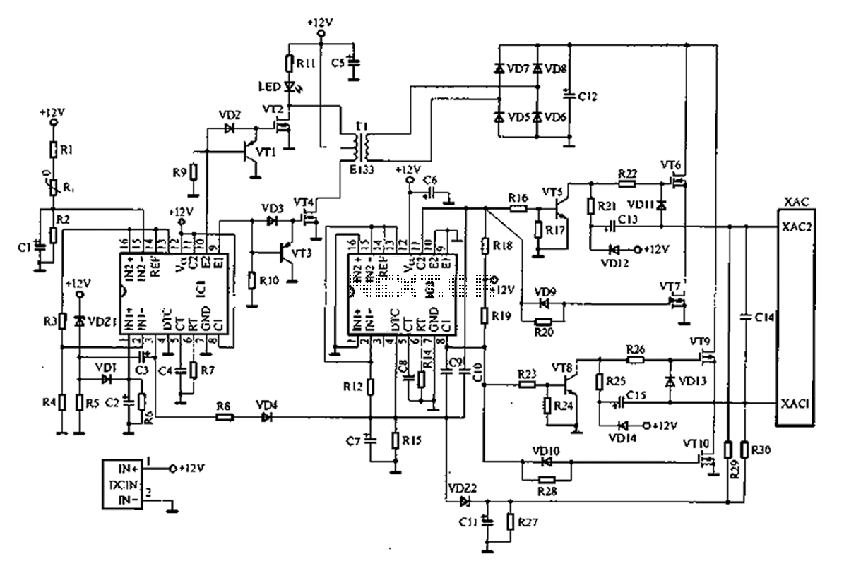
MC2833 radio transmitter Typical application circuit

The MC2833 and MC2831 integrated circuits are designed for efficient radio frequency transmission applications. The circuit operates at a frequency of 49.7 MHz, which is suitable for various short-range communication tasks. The primary function of this circuit is to modulate audio signals onto a carrier wave, allowing for the transmission of information over radio waves.
The circuit typically includes an oscillator stage that generates the desired frequency, a modulator stage that combines the audio input with the carrier wave, and a power amplifier stage that boosts the signal strength for effective transmission. The antenna connected to the output of the power amplifier radiates the modulated signal into the surrounding environment.
In practical applications, the MC2833 and MC2831 circuits can be used in wireless microphones, remote controls, and other devices that require reliable radio communication. The design ensures minimal distortion and efficient power usage, which are critical for maintaining signal integrity and extending battery life in portable devices.
For optimal performance, careful consideration must be given to the layout of the circuit board, component selection, and tuning of the oscillator to achieve the desired frequency stability and output power. Additionally, proper shielding and grounding techniques should be implemented to minimize interference and enhance the overall performance of the transmitter circuit.MC2833 MC2831 radio transmitter dedicated circuit is improved.Radio transmitter typical application circuit this circuit generates a high frequency 49.7MHz signal transmitted by the antenna out.
Related Circuits
A common car inverter circuit and its working principle. Car inverter specifications include: Input voltage: DC 10V to 14.5V; Output voltage: AC 200V to 220V with a tolerance of 10%; Output frequency: 50Hz with a tolerance of 5%; Output...
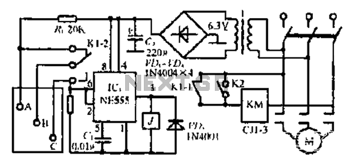
After the 3.40V power supply, the voltage is reduced to 6.3V through a full transition rectification using VDi and V sulfone. The C1 filter provides voltage stabilization after the caution circuit operates at the NE555 voltage level. When the...
The circuit was constructed using a few components powered by a 9 V battery for sensing the presence of bugs transmitting within the frequency modulation range. Frequency Modulation (FM) transmits its signal or information over a carrier wave by...
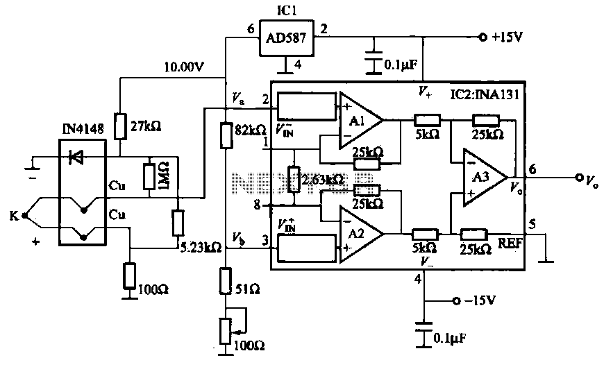
The AD587 is a precision voltage reference providing a 10 V output, generated using a 27 kΩ resistor along with a compensation diode (1N4148) and a thermocouple. This setup connects to the VI + N terminal of a differential...
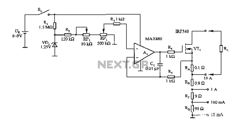
The FIG load test is a control circuit designed for external loads up to 10A, commonly utilized in drive test power applications, power amplifiers, LED solenoids, and relays. It is capable of handling various resistive loads and features a...
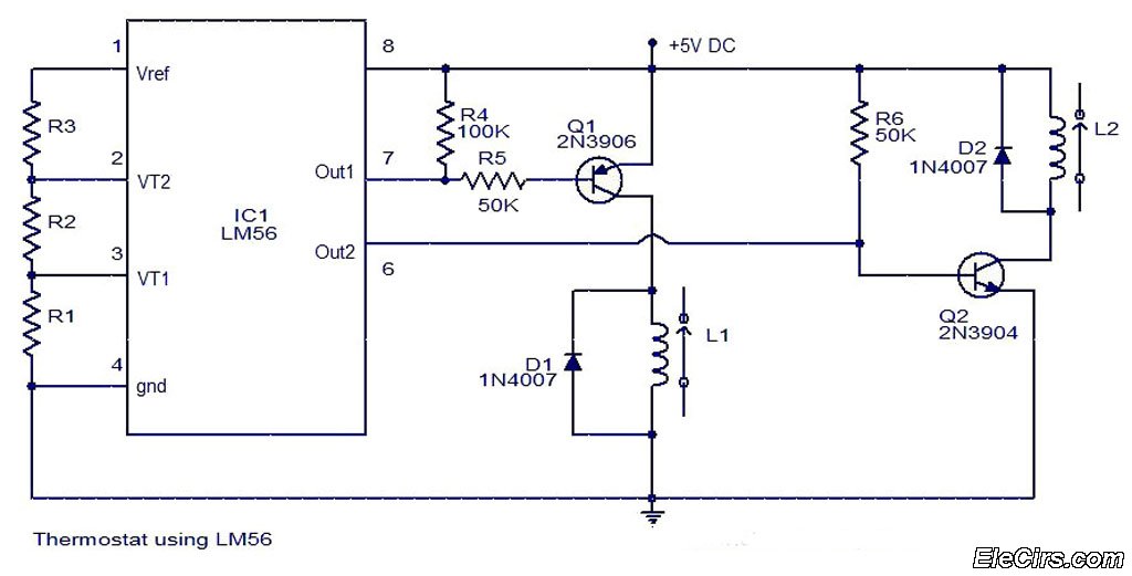
The LM56 Thermostat Project Circuit Diagram includes a schematic for the LM56 thermostat. The values of resistors R1, R2, and R3, which determine the required trip points VT1 and VT2, can be calculated using the following equations: VT1 =...