
Passive tone control circuit
The passive tone control circuit is an essential component in audio signal processing, allowing users to tailor the sound characteristics of an audio system. This circuit utilizes a straightforward design that leverages passive components, making it cost-effective and easy to implement.
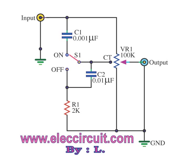
The low-frequency filter pathway consists of R1 and C1, which form a first-order low-pass filter. The resistor R2 is connected in series to provide a variable resistance that can be adjusted using the variable resistor VR1. This arrangement allows for the attenuation of high-frequency signals, enabling the user to enhance the bass response of the audio output. The values of R1, C1, and R2 can be selected based on the desired cutoff frequency, which determines the range of frequencies that will be affected by the adjustment.
In the high-frequency filter pathway, components C4, R5, and C5 form a first-order high-pass filter. Similar to the low-frequency pathway, VR2 is used to vary the resistance of R5, allowing for fine adjustments to the treble frequencies. The interaction between C4 and R5 dictates the cutoff frequency for the high-pass filter, enabling the user to boost or reduce the presence of higher frequency sounds.
The final output of the circuit is achieved by combining the outputs from both filters through R3 and R4. This configuration ensures that the modifications made to both low and high frequencies are preserved in the final audio signal. Additionally, C3 plays a crucial role in filtering out unwanted noise, enhancing the overall quality of the audio output.
In summary, the passive tone control circuit is a valuable tool for audio enthusiasts and engineers, providing an effective means of shaping sound quality without the need for complex power supplies or active components. Its simplicity and effectiveness make it a popular choice for various audio applications, from home audio systems to professional sound equipment.The Passive tone control circuit be the circuit fines the bass that has no the expansion but will give kind equipment R and C. It perform filter frequency then the circuit that build easy and must not use power supply. By can concede the porch with part power amplifier of output immediately. When feed input come in sound signal will that come in t o separate is 2 the way by first way will change to come to a part filters low frequency for example R1, C1, C2, R2. By have VR1 be formed fine expansion way ratio low frequency is or sound in the sense of second a signal will change to come to a part filters tall frequency for example C4, R5, C5 by have VR2 be formed fine the value of tall frequency or treble a signal that depart a part filter tall frequency and low change R3 and R4 congregate then go out still output.
By have C3 perform eradicate the noise goes out. 🔗 External reference
Related Circuits
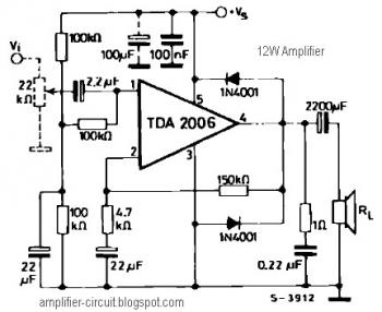
The power amplifier IC TDA2006 provides high output current and has very low harmonic and cross-over distortion. Furthermore, the device incorporates an original (and patented) short circuit protection system that automatically limits the dissipated power to keep the working...
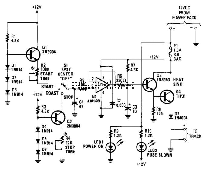
The unique aspect of this control is its momentum feature, which enhances realism. The circuit is designed to operate efficiently for trains that draw up to 1 A at 15 V. None of the components are critical. In the...
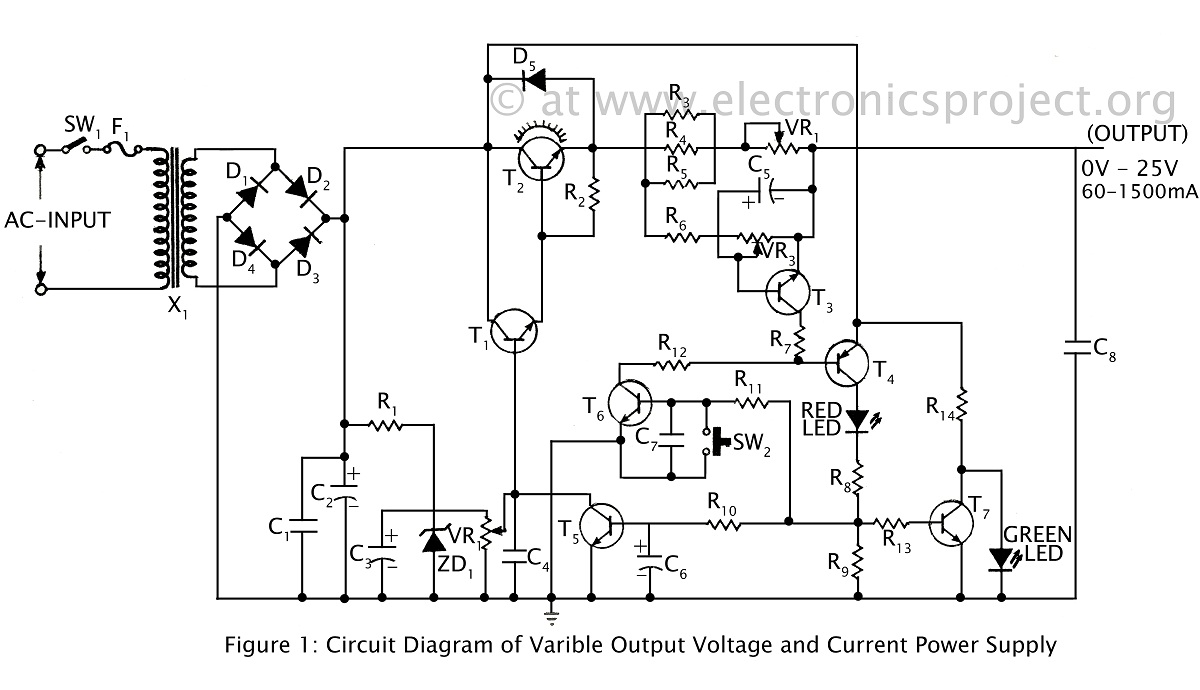
A ripple-free, short-circuit protected variable output voltage and current power supply is presented on this website as a verified project. The circuit diagram includes a description of various power supply circuits. This power supply circuit is designed to provide a...
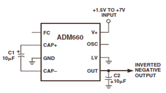
The ADM660 is a charge-pump voltage converter that can either invert the input supply voltage or double it. The schematic below depicts the ADM660 Voltage Inverter Circuit Configuration Diagram. This inverting schematic is ideal for generating a negative rail...
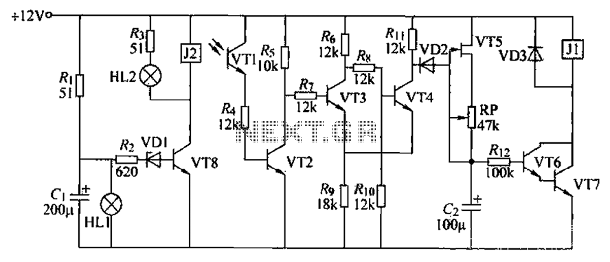
A blocking material monitoring circuit is presented. When the optical path is obstructed by the material, the phototransistor VT1 turns off, which subsequently turns off transistors VT2, VT3, and VT4. This arrangement is coupled to a flip-flop configuration. When...
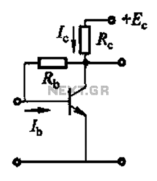
Basic reference bias circuit using a transistor with negative voltage feedback. The basic reference bias circuit utilizing a transistor with negative voltage feedback is designed to provide a stable output voltage or current that is largely independent of variations in...