
Ripple-free Short-circuit protected variable output voltage and current power supply.

This power supply circuit is designed to provide a stable output voltage and current while ensuring protection against short circuits and ripple voltage. The key features of this circuit include adjustable output settings, which allow users to modify the voltage and current levels according to their specific requirements.
The circuit typically incorporates a linear voltage regulator or a switching regulator, depending on the desired efficiency and output characteristics. The use of capacitors in the design helps to filter out any ripple voltage, ensuring a smooth and stable output. Additionally, the implementation of a short-circuit protection mechanism, such as a fuse or a current-limiting circuit, safeguards the power supply from damage due to excessive load conditions.
The schematic diagram for this power supply will usually include essential components such as transformers, rectifiers, voltage regulators, capacitors, and protection devices. Each component plays a crucial role in the overall functionality of the power supply, contributing to its ability to provide reliable and adjustable power output.
In summary, the described power supply circuit is an essential tool for various electronic applications, offering flexibility and safety features that enhance its usability in different scenarios.Ripple-free, Short-circuit protected variable output voltage and current power supply in this website is verified project.circuit diagram with description of power supply circuit various power supply circuit . 🔗 External reference
Related Circuits
You need a power supply for a project, but only have a DC adapter available, so you can't use my AC power adapter trick (Project 05). This little project came about because a reader had just this problem, and...
The foundation of this amplifier is detailed in Project 03, which does not claim to be cutting-edge; the base design is over 20 years old. It is straightforward to assemble, utilizes readily available components, and is stable and dependable....
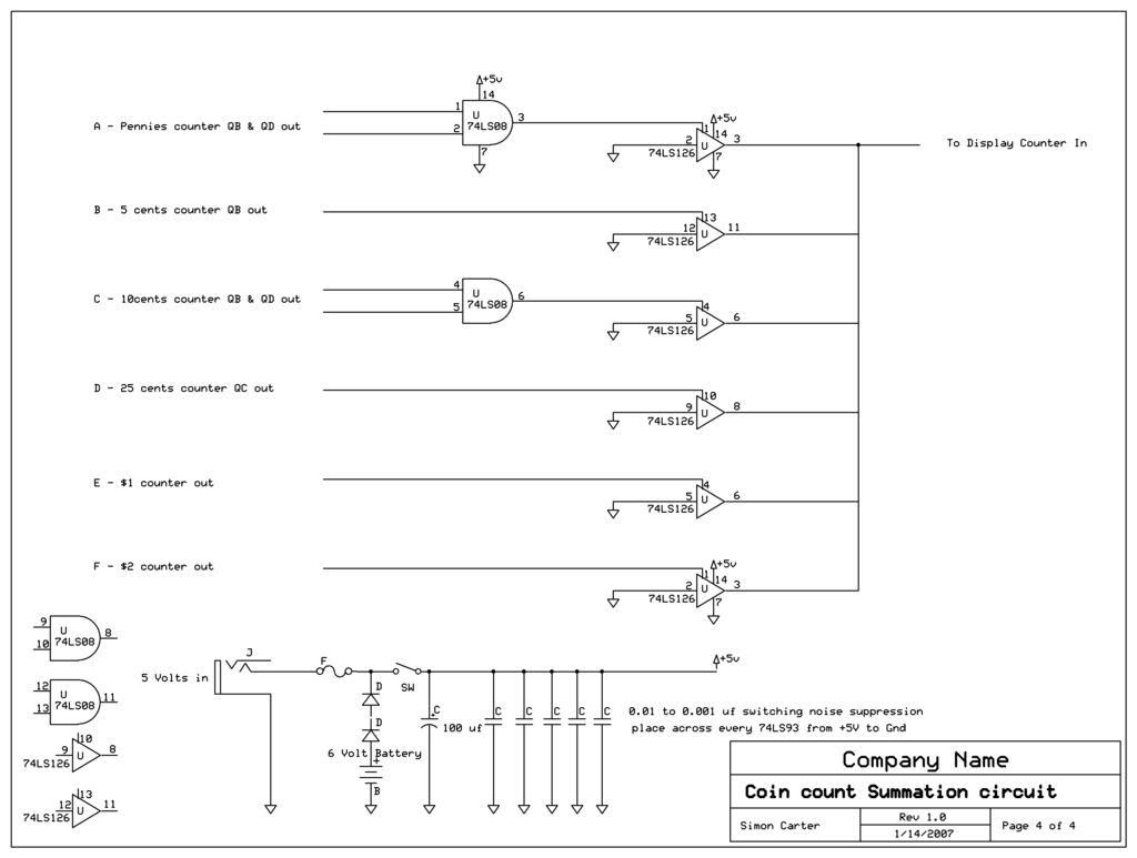
The outputs of all coin counters are summed in a 74LS126 tri-state buffer, which is used to connect all the counter outputs to the input. The circuit utilizes a 74LS126, a quad buffer/driver with three-state outputs, to manage the outputs...
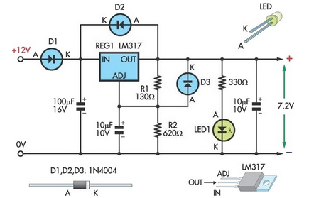
This circuit allows an external 12V sealed lead-acid (SLA) battery to power a camcorder that typically operates with an internal 7.2V battery. Obtaining such batteries for older camcorder models can be challenging and costly. The circuit functions as a...
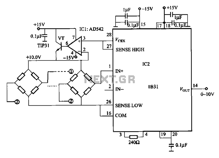
The 1832 low drift input has a temperature coefficient of 0.07 µV/°C (RTI, G 500) and exhibits excellent linearity with a maximum deviation of 0.005%. It can drive resistive loads greater than 120 ohms in a bridge excitation circuit,...
This circuit generates a constant current, constant voltage switched-mode power supply (SMPS). It is designed to efficiently charge a battery using a constant current, constant voltage approach. The circuit operates as a constant current, constant voltage SMPS, which is crucial...