
Radio-controlled toy car
The transmitter circuit begins with the oscillator, which is responsible for generating a stable radio frequency signal. Transistor Q1 (9016) functions as the main active device in this oscillator configuration, providing the necessary gain and switching capabilities. The frequency of oscillation is finely tuned by the crystal Y1, ensuring that the emitted signals remain within the designated frequency band for radio communication.
The oscillator's performance is significantly influenced by the inductor components L1 and L2, which are carefully selected to resonate with the crystal frequency. These inductors, in conjunction with T1, form a tank circuit that is essential for maintaining the stability and purity of the oscillation. The design must ensure minimal distortion and a clean signal output, which is crucial for effective communication between the transmitter and receiver.
The receiver circuit is designed to capture the radio signals transmitted by the oscillator. It typically includes an RF amplifier to boost the received signal strength, followed by a demodulator that extracts the original control signals from the modulated carrier wave. The receiver's performance is equally critical, as it must effectively filter out noise and interference while maintaining the integrity of the control commands sent to the toy car.
The entire system is powered by a suitable DC power source, which must be regulated to ensure consistent operation of both the transmitter and receiver circuits. Proper grounding and shielding techniques should also be implemented to minimize electromagnetic interference, which can adversely affect the performance of the circuit.
Overall, this radio-controlled circuit diagram is a fundamental representation of how toy cars can be remotely operated, showcasing the essential components and their roles in the transmission and reception of radio signals. Understanding each part's function and interaction is vital for troubleshooting and enhancing the circuit's performance in practical applications.This circuit is a circuit diagram of the radio-controlled, usually in the toy car application children. Circuit diagram consists of 2 parts of the circuit sender and receiver circuits. To the circuit sending radio signals generated by the oscillator circuit formed by transistors Q1 9016, operating frequency of the oscillator is determined by the crystal Y1 is worth 27.145 MHz.
A very critical part of this oscillator circuit is T1, L1 and L2, which specifically discussed separately at the end of. 🔗 External reference
Related Circuits
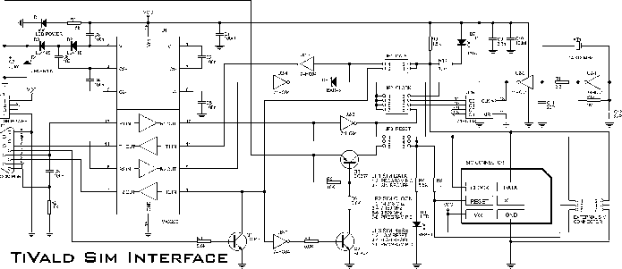
The electronic adapter derives its power supply from the VCC line of the smartcard reader device, or alternatively, an external 5 V supply can be utilized. The RST line of the card slot is connected to one of the...
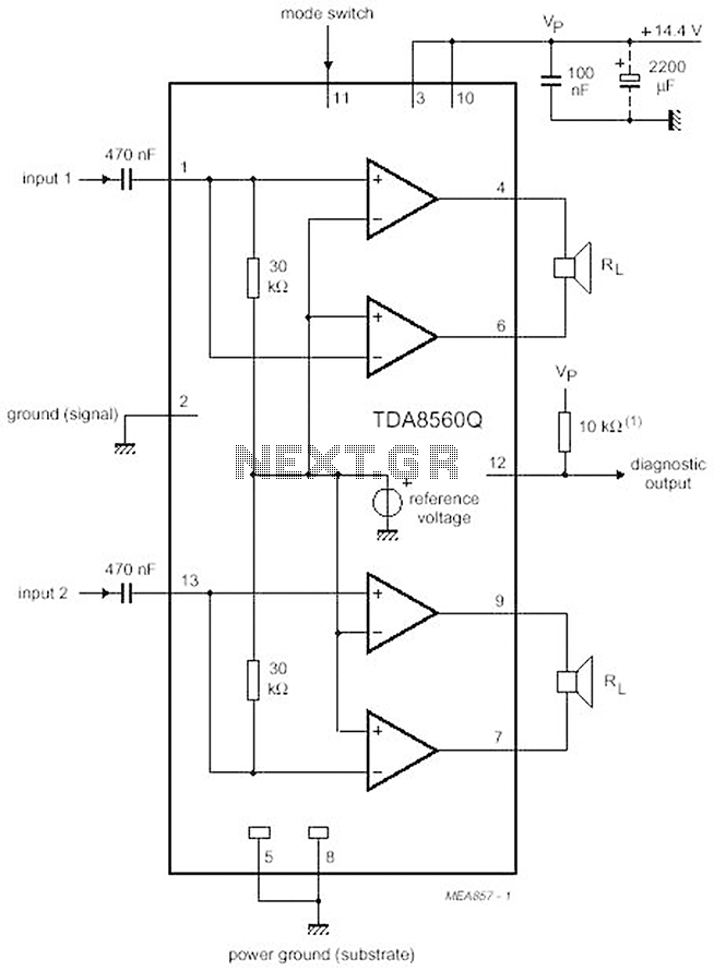
The proposed scheme is straightforward, requiring only a few external electronic components, making it suitable for car audio construction. The output power ranges from 2 to 4 Ohms, providing 2 x 30 W (with a maximum of 2 x...
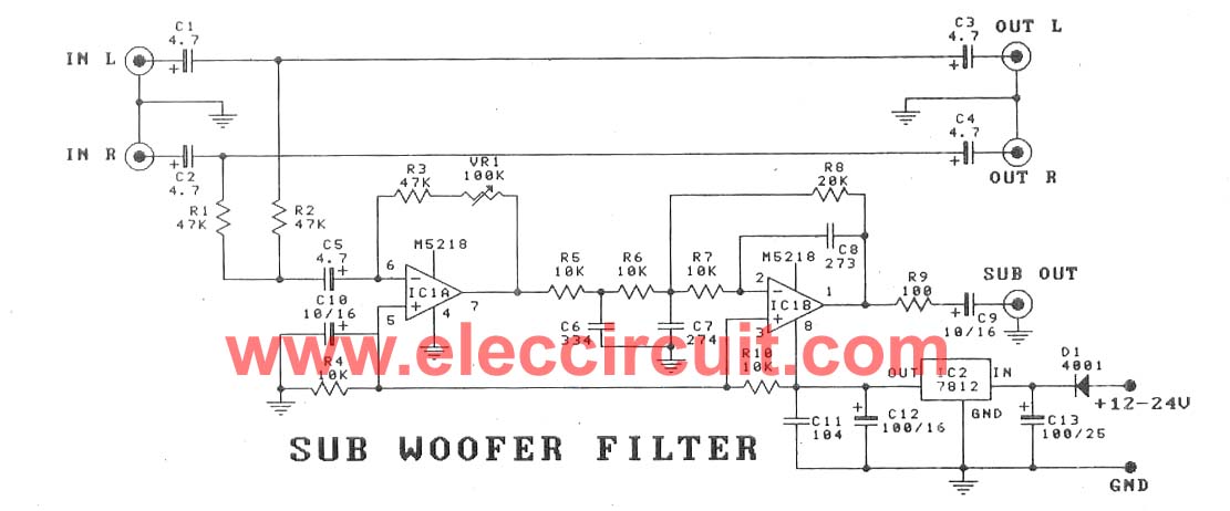
This subwoofer filter set is suitable for use with a high-quality car audio system. The circuit is designed to operate with a 12-volt DC power supply. The subwoofer filter set serves as an essential component in enhancing the audio experience...
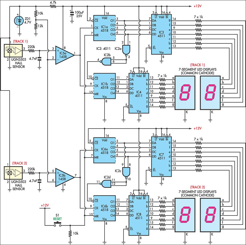
AFX slot car sets are enjoyable, and the experience can be enhanced with a lap counter. This circuit counts from 00 to 99, featuring independent counters for each track. The sensing device utilized is a Hall effect sensor (UGN3503),...
According to current legislation in many countries, vintage cars must also be fitted with a rear fog lamp. Modern vehicles incorporate circuitry associated with the fog lamp switch to prevent the fog lamp from activating when the lights are...
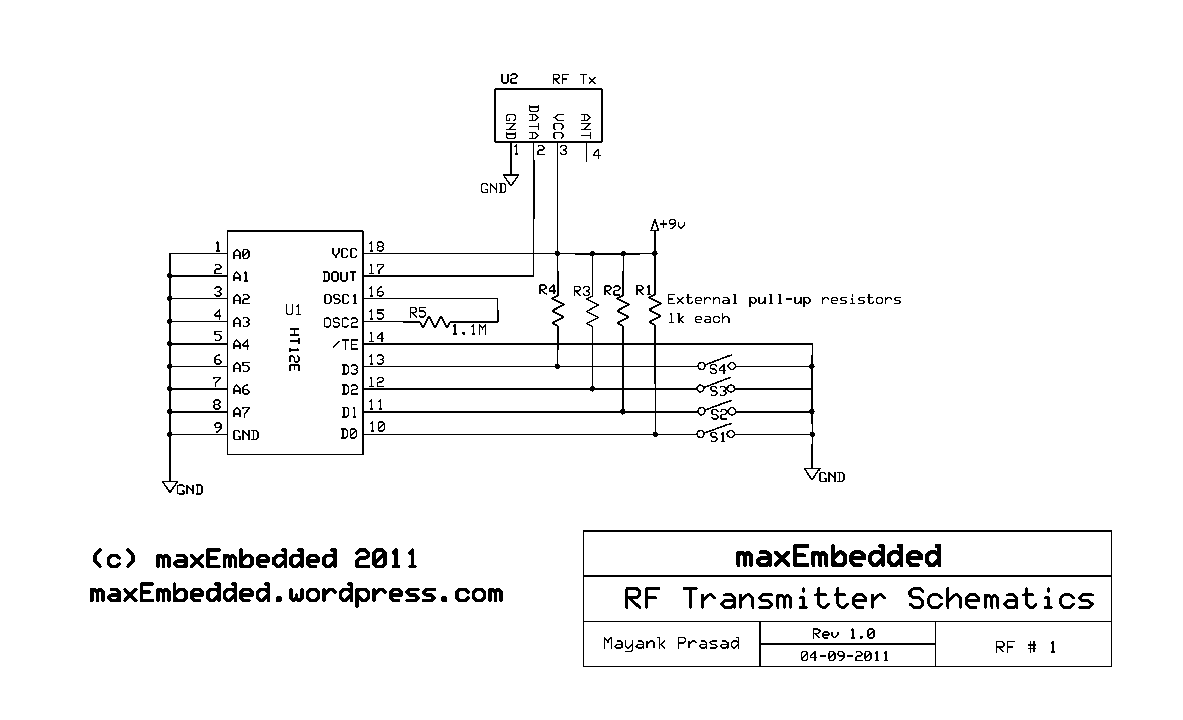
This article is authored by Yash Tambi, a Core Committee Member of roboVITics. It discusses RF-controlled robots, which are among the simplest types of robots. The essential components include a few readily available integrated circuits (ICs), a 433 MHz...