
making an rf car
The L293D motor driver IC is introduced, which is a popular 16-pin device. It features 8 pins on each side, including 2 enable pins, 1 VSS pin, 1 VS pin, 4 ground pins, 4 input pins, and 4 output pins. The enable pins, when activated (set to high), allow the corresponding sections of the IC to function. Enable 1 activates the left side for inputs and outputs, while Enable 2 does the same for the right side. The VS pin receives the voltage intended for the motors, while the output pins provide this voltage, typically reduced by 1.8 to 2 volts due to the internal gates. The state of the input pins determines the output; if an input pin is high, the corresponding output pin is also high, and vice versa. Notably, if the input pins are left unconnected or set to high, the output pins will produce a signal.
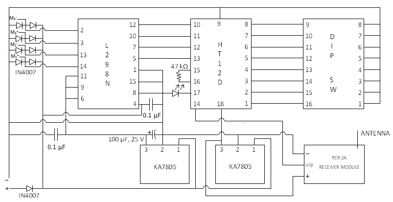
The L293D can control up to four motors simultaneously, with the negative terminals of each motor connected to ground and the positive terminals connected to the output pins. For bidirectional control, only two motors can be connected as per the circuit schematic.
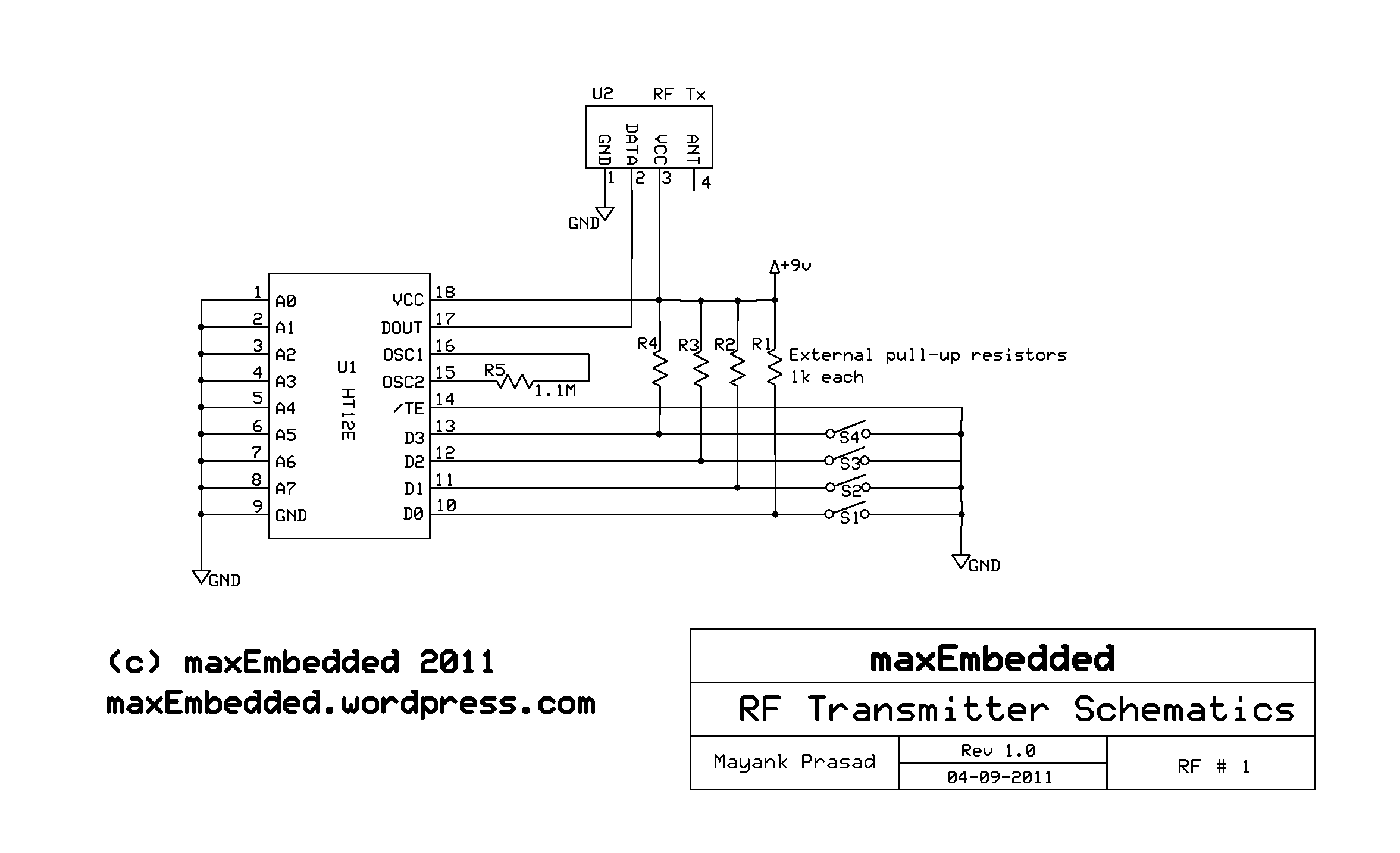
The HT12E encoder is also discussed, which converts digital signals into a format suitable for transmission via electromagnetic signals. This 8-bit encoder is commonly used with 433 MHz wireless modules and consists of 18 pins, with Osc1 pins serving as the oscillator input and output, typically connected with an external resistor. The communication between the transmitter and receiver is dependent on the configuration of the address pins on both ICs, which must match for proper operation. A gamepad can be utilized for inputs, functioning in an active low configuration—producing a low signal when a button is pressed and a high signal when released.
The HT12D decoder is introduced, which decodes signals for transmission through electromagnetic signals. Similar to the HT12E, it is an 8-bit device with 18 pins and Osc1 pins connected through an external resistor. Pull-up resistors of 100kΩ are connected across the D8 to D11 pins, with their other ends either grounded, set to high, or left floating based on the desired default output from the HT12D.
In summary, this article provides an overview of the components and functionalities of RF-controlled robots, detailing the roles of the LM7805, L293D, HT12E, and HT12D ICs in the circuit design.This is an article written by a one of my readers, Yash Tambi, Core Committee Member, roboVITics. Do read this post and pitch in your comments below regarding this. Thanks! RF controlled bots are the most simple of their kind. All you need are a few ICs, which are easily available in the market, a 433Mhz Transmitter and Receiver module, and the u sual wires, resistors etc. Theoretical information related to this can be found in this post, where Mayank discussed about RF module interfacing. Using the LM7805 IC is quite simple. It is used to convert the input varying supply (usually 9-18 volts) to a stabilized 5 volts supply, which is used to drive the circuitry.
We start with the L293D. L293D is a popular motor driving IC. It is a 16 pin IC. The IC has 8 pins on both the sides. It has 2 enable pins, 1 VSS pin, 1 VS pin, 4 ground pins, 4 input pins and 4 output pins. Though not required here, but in case you wish to learn how to interface L293D with a microcontroller, you could refer to this post by Mayank. Enable the enable pins, when are given true, (i. e. 1) then they enable the respective part of the IC. The enable 1 chip enables the Left part of the IC for inputs and outputs, and so does the Enable 2 does to the right part of the IC.
VS this pin is given the voltage that we have to supply to the motors. This voltage comes out through the output pins. Due to the gates used in the IC, the output is usually 1. 8 to 2 volts less than the Vs. Input the input pin decides whether output has to be given to he respective output pin or not. When the Input is true, then output is also 1 in the respective output pin. When input in the Input pin is 0, and then output in the respective output pin is also 0. Note- When no input is given to the inputs pins (i. e. they are left floating) or 1 is given, there is an output from the output pins. Its only when 0 (ground) is given to the inputs, when the output is zero for the corresponding output pin. The L293D IC can be used to control a maximum of 4 motors simultaneously. When 4 motors are connected to the IC, then for operation, -ve of each of the motors is connected to the GND, and the +ve terminal to the outputs.
For bidirectional control, you can connect only two motors simultaneously as per the circuit diagram below: The next IC is HT12E. The HT12E is an encoder. It converts digital signals into suitable form to be transmitted through EM signals. It is an 8-bit Encoder. The HT12E is usually used for 433 MHz wireless modules. It is an 18 leg IC. Osc1: 2 these pins are the oscillator input and output pins. For the ordinary circuit, they are connected to each other with the help of an external resistor. Note - How does a transmitter know to which receiver it has to send the signal to It depends on the configuration of the address pins on Both the ICs.
For the Tx-Rx pair to work, they should have the same configuration of the address pins. You can also use a gamepad for the inputs. Remember, gamepads are designed to be active low in configuration i. e. when you press a key in the gamepad, it sends out 0` and when left floating, it gives 1`. The next IC is HT12D. The HT12D is a decoder. It decodes signals into suitable form to be transmitted through EM signals. It is an 8-bit Encoder. The HT12D is usually used for 433 MHz wireless modules. It is an 18 leg IC. Osc1: 2 these pins are the oscillator input and output pins. For the ordinary circuit, they are connected to each other with the help of an external resistor. Pull-up resistors of 100K © are connected across D8, D9, D10, D11 pins. The other end of the resistors may be either grounded, or given 1, or left floating depending upon what we want as the default value from the output pins of HT12D. And that`s it for now! Any kind of queries and discussion, please leave a reply below and I will be more than happy to get back to you!
:) You can also subscribe to maxEmbedded for more i 🔗 External reference
Related Circuits
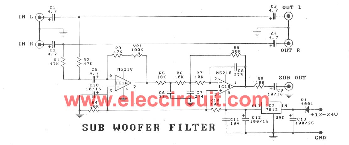
This subwoofer filter set is suitable for use with a high-quality car audio system. The circuit is designed to operate with a 12-volt DC power supply. The subwoofer filter set serves as an essential component in enhancing the audio experience...
A basic RC car is being constructed, which includes an LED in the receiver circuit that illuminates when a button on the remote is pressed. The described RC car project incorporates a receiver circuit that activates an LED indicator in...
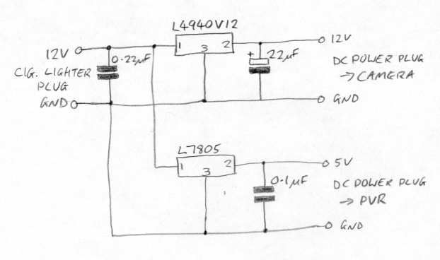
There is now no need for a separate camera and recorder; for a lower cost, an integrated dash camera that records in HD can be obtained. The Techmoan blog offers reviews on these devices. This text describes the installation...
When we step on the car's brake, then together with the classic rear STOP, the third STOP which is situated in the middle of the back half of the car also switches ON. This is the classic function, found...
The SN75604, which features input control logic and requires only a single supply rail, can be utilized in light activation sensors and alarm drivers. The device's Vqq and enable inputs are connected to a voltage lead from the light...
This is an anti-theft alarm with wireless connectivity, referred to as the Anti-Theft Car Wireless Alarm. The FM radio-controlled anti-theft alarm can be utilized with any vehicle that operates on a 6 to 12-volt DC supply system. The mini...