
Sawtooth Wave Generator

The sawtooth wave generator is an essential circuit used in various applications, including audio synthesis, signal modulation, and timing applications. The fundamental operation of this circuit is based on the linear charging and rapid discharging of a capacitor.
The core components typically include a resistor, a capacitor, and an operational amplifier or a transistor, depending on the design requirements. The capacitor charges through the resistor, creating a linear voltage increase over time. Once the voltage across the capacitor reaches a predefined threshold, a comparator or a transistor switches states, rapidly discharging the capacitor to initiate the next cycle of the waveform.
The frequency of the sawtooth wave can be adjusted by varying the resistor and capacitor values, allowing for flexibility in output frequency. The output can be taken from the junction of the resistor and capacitor or directly from the output of the comparator or transistor.
In a typical schematic, the power supply is connected to the operational amplifier or transistor, providing the necessary voltage levels for operation. The output waveform is characterized by a linear rise followed by a sharp drop, which is the defining feature of the sawtooth wave.
This circuit can be simulated using electronic circuit simulation software, which provides a visual representation of the waveform and allows for real-time adjustments to component values. This simulation capability aids in understanding the behavior of the circuit under various conditions and assists in troubleshooting and optimization before physical implementation.This is the Sawtooth Wave Generator circuit diagram with the detailed explanation of its working principles. The electronic circuit simulator helps you to design the Sawtooth Wave Generator circuit and to simulate it online for better understanding..
🔗 External reference
Related Circuits
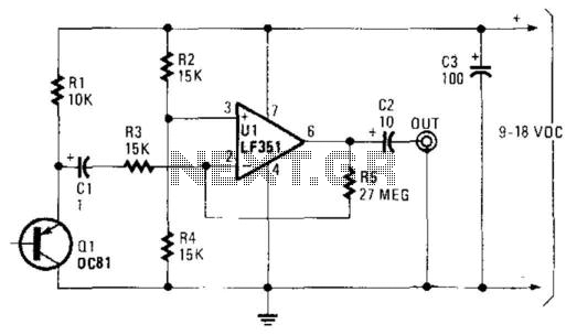
A germanium transistor (Ql) is utilized as a noise generator within the audio frequency range. The operational amplifier (Ul) serves as a high-gain amplifier. The specific characteristics of Ql are not critical; most germanium transistors are generally effective for...
A high voltage power supply DC converter that operates between 3V to 500V has been suggested for use with Geiger tubes. However, during simulation, the output remained at nearly 9V, which matches the input voltage. The schematic drawn has...
The 16F84 has 13 outputs. All 13 can serve as inputs, but only 12 are normal outputs, one is an open-drain. An open-drain output has no active pull up - you have to provide an external (passive) pull up....
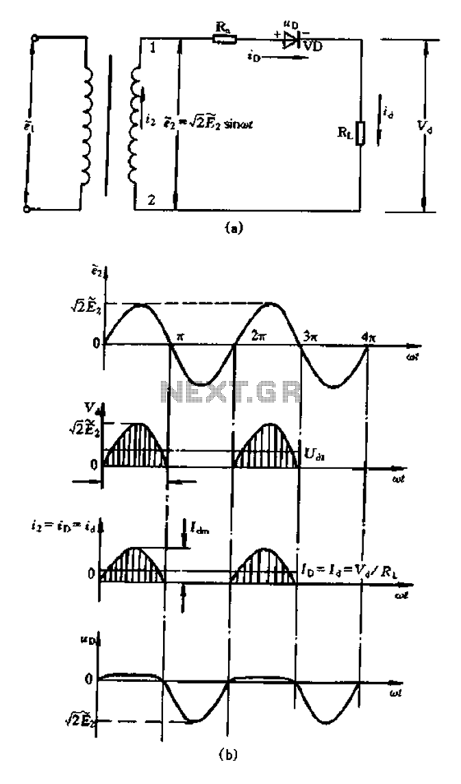
A bridge rectifier capacitor filter serves as a primary power supply for current amplifier circuits. This power supply configuration is straightforward and offers enhanced performance. The bridge rectifier circuit is a full-wave rectifying circuit, meaning it converts both the...
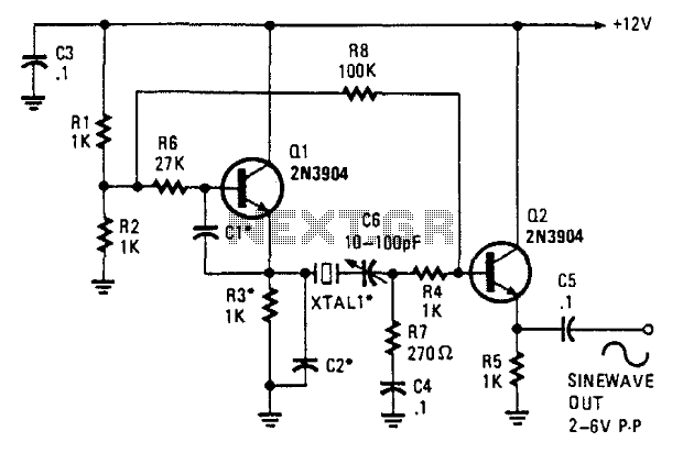
This oscillator employs two transistors and operates the crystal in its fundamental mode. Capacitors CT and C2 should be approximately 2,700 pF for 1 MHz, 680 pF for 5 MHz, and 330 pF for 10 MHz. A capacitance of...
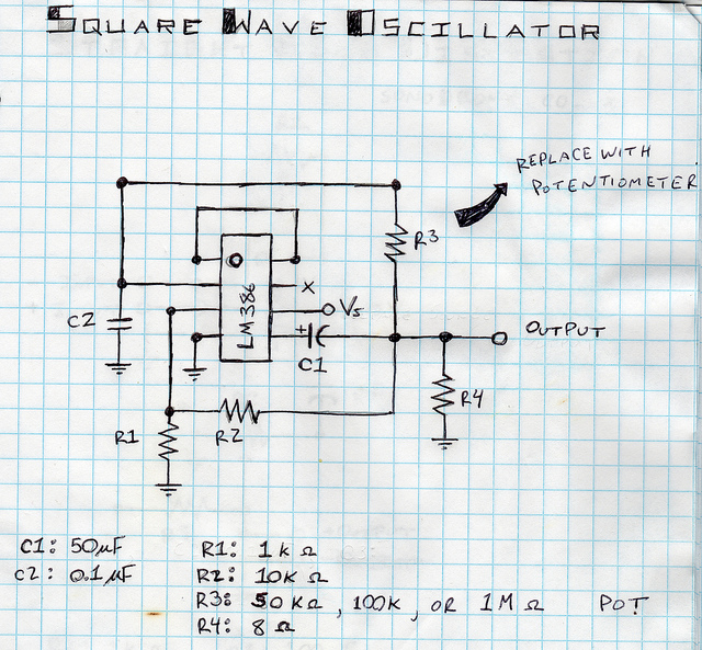
This is a square wave oscillator (digital, similar to 8-bit music). It is based on the LM386 amplifier integrated circuit, which is also the foundation for the mini guitar amplifier. The design includes a simple power switch connected to...