
Half-wave rectifier circuit principle

The bridge rectifier circuit comprises four diodes arranged in a bridge configuration, enabling it to rectify both halves of the AC waveform. When an AC voltage is applied to the input terminals of the bridge, the diodes conduct in pairs, allowing current to flow through the load during both the positive and negative cycles. This results in a continuous output voltage across the load, which is then smoothed by the capacitor filter.
The capacitor filter is connected in parallel with the load and serves to reduce the ripple voltage present in the rectified output. During the conduction phase, the capacitor charges up to the peak voltage of the rectified output. When the diodes stop conducting, the capacitor discharges slowly, supplying current to the load and thereby maintaining a more constant voltage level. The effectiveness of the capacitor filter is determined by its capacitance value; larger capacitance results in lower ripple voltage and a more stable DC output.
In summary, the bridge rectifier capacitor filter is an essential component in power supply circuits for amplifiers, providing a reliable and efficient means of converting AC to DC while ensuring that the output voltage remains stable and suitable for further processing by electronic devices. Bridge rectifier capacitor filter is one of the main power supply of the current amplifier circuit, such a power supply circuit configuration simple one, better performance. A bridge rectifier circuit is a full-wave rectifying circuit, i.e. in the AC power supply both positive and negative half cycles have a DC output. To illustrate how it works, start with about half crossing the rectifier circuit. Figure 7-1 is a half-wave rectifying circuit diagram of the road works. In the drawing power transformer secondary AC voltage e2 E pumping. E2 sin called sin should be the foundation, which the transformer secondary AC voltage E2 has saved values. AC positive half cycle, l is a positive side, 2 side is negative, rectifier VD conduction, the output current to the load RL o in the negative half cycle, l side is negative, the second end is positive, reverse bias rectifier VD nonconductive, no current load circuit.
Therefore, during each cycle of the AC voltage, the load current through only half cycle current, load voltage Vd is unidirectional pulsating DC voltage, shown in Figure 7-1 (b). A cycle of AC Ji is 2, the entire stream after the DC output voltage can be expressed as:
Related Circuits
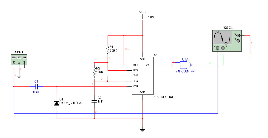
This is a very simple circuit utilizing a 555 timer IC to generate a square wave of frequency that can be adjusted by a potentiometer. With values given, the frequency can be adjusted from a few Hz to several...
Switching regulator subsystems are designed for use as DC to DC converters. The 3V to 40V DC converter circuit utilizes switching regulators, which are increasingly favored over linear regulators due to the demand for higher conversion efficiency in modern...
This circuit is designed to control the mains voltage by switching it on and off at intervals ranging from just under a second to up to 10 minutes. It is particularly useful for testing mains-operated equipment over extended periods...
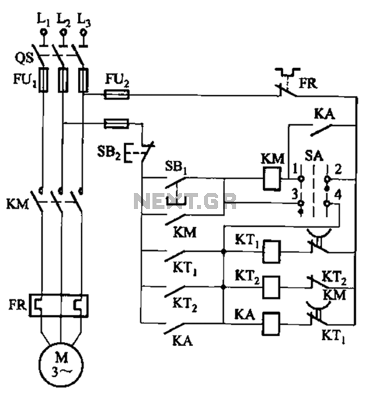
The circuit illustrated in Figure 3-78 utilizes two relays for automatic control, featuring a more complex line structure. This configuration allows for intermittent motor operation. Additionally, it can operate continuously when switch SA is positioned to the right. The circuit...
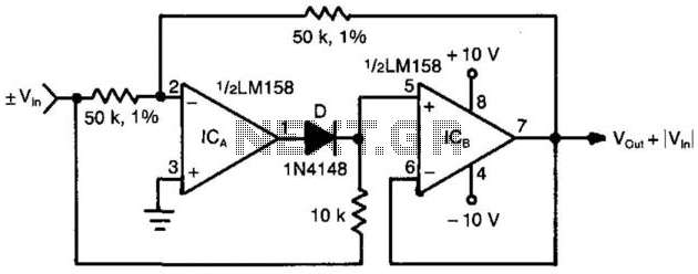
When the input voltage is positive, the output of ICA is negative, resulting in diode D not conducting; therefore, the output of ICB is positive. Conversely, when the input is negative, the output of ICA becomes positive. Diode D...
Hello everyone. I need some help. I have constructed a PWM and PPM circuit. The output is functioning smoothly, but I am experiencing some problems and I am not very experienced. The PWM (Pulse Width Modulation) and PPM (Pulse Position...